P&ID Drawing Tool
Piping and Instrumentation Diagram (P&ID) is a schematic layout of a processing plant, which shows the installed units including process equipment, instrumentation and control devices, and piping connecting them. It is a fundamental diagram for each standardized engineering project. P&ID represents graphically a process system, the key components of a plant or industrial facility, and describes the operation processes within a plant.
Piping and Instrumentation Diagram is usually created at the plant design stage and then is used at all further stages of plant building and operation. P&IDs are applied in the field of instrumentation, control, and automation. The equipment may differ based on the industry or manufacturer. Most often these include storage tanks, sensors and control valves, surge tanks, pumps, fans, heat exchangers, distillation columns, reactors, actuators, reducers, increasers, drains, vents, flow elements, vessels, separators, heat equipment, fire and safety equipment, instrumentation, and many other specific equipment. P&ID diagram shows the functional relationships between the equipment and obligatory details about the piping fittings connecting the units.
Each piece of equipment has its own function and plays a specific role in the plant's operation. Vessels are containers of various sizes and volumes to store different fluids; these include cylinders, tankers, columns, etc. Valves include rotameters, orifices, and other equipment to control, regulate, and direct the flow of fluids through piping. Pumps are used to move fluids in and out of other objects, raise and compress fluids using the mechanisms of suction or pressure. Heat exchangers include boilers, condensers, and other equipment used for transferring heat. The use of instruments for measuring and tracking different quantities is also widespread in plants. These include indicators, controller transmitters, recorders, and other tools to track temperature, pressure, flow, angle, and other characteristics.
Piping and Instrumentation Diagrams are used in many fields and have great advantages. They are popular in the power generator sector, metallurgical industry, air conditioning industry, refinery industry, and so on. P&IDs are essential engineering documents to design and document the manufacturing processes, outline in detail chemical or mechanical steps, define guidelines and standards for facility operation, safety parameters and rules, develop project specifications, and estimate capital project cost. P&ID is the best way to take information about processes, materials, and other features, and look for the solution for usual and unexpected issues during the system development or operation.
Piping and Instrumentation Diagrams are useful for engineers, designers, builders, and many other technical specialists including regulatory agencies. They help to manage the operation of plants, personnel behavior, and company policies, ensure employees and environment safety, control emissions of chemical plants, decrease pollution, treat water, etc. P&IDs contribute to ensuring high performance of enterprises on a national and local level. They are useful when training new workers and contractors working in the plant and are essential to make changes, remove the issues, increase efficiency of the engineering processes, check safety, improve collaboration among employees. P&IDs enable the personnel to evaluate the processes accurately, efficiently control plant operation, prepare and implement safety control systems, introduce industrial automation.
Example 1. P&ID Drawing Tool in ConceptDraw DAGRAM
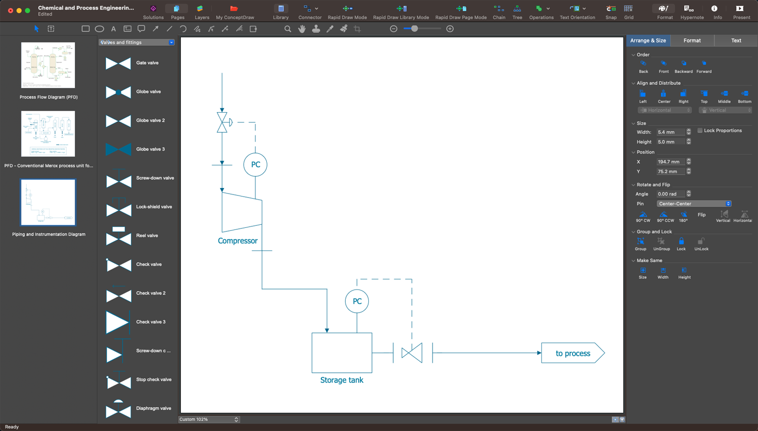
The standard notation with specific shapes and symbols is used for P&IDs and serves as a unified global symbolic language making these diagrams understandable to engineers and designers from all over the world, and ensuring efficient communication of technical specialists. The notation includes symbols for compressors, motors, turbines, conveyors, vacuums, and other mechanical tools and hardware elements, symbols for pipes, vessels, separators, pumps, valves, and many other instruments and equipment. Knowing the meaning of various symbols is vital to understanding a P&ID correctly.
In addition, the diagram usually includes the specifications, indication of used materials, substances possible to transport, seismic category, equipment rating or capacity, interconnections reference, insulation requirements, quality level, and other characteristics. Mechanical equipment usually comes with names and numbers, valves include identifications. The diagram should include flow directions, control inputs and outputs.

Example 2. Chemical and Process Engineering Solution Libraries
ConceptDraw DIAGRAM enhanced with Chemical and Process Engineering solution is a powerful engineering system design software useful for all engineers to develop a plant or industrial facility project, design manufacturing processes, visualize the physical sequence of the equipment. Design efficiently your processing plans, create professional-looking P&IDs, show the piping and associated parts of a physical process flow, and track the operation of a plant.
ConceptDraw DIAGRAM is a handy P&ID drawing tool for all beginners and professionals. This vector drawing software helps to design a wide range of P&ID diagrams efficiently and use them to create specifications, reports, presentations, and other unique and cohesive visual content. The Chemical and Process Engineering solution includes a large collection of predesigned vector design elements — vessels, pumps, valves, fittings, industrial and heating equipment, and other instruments, which easier the drawing process. The included samples are great examples and customizable templates are the best basis for your own diagrams no matter the complexity of your process or system. ConceptDraw DIAGRAM supports various formats and you can export your diagrams in a desired graphical or file format and share them easily.

Example 3. Conventional Merox Process Unit for Sweetening Jet Fuel or Kerosene
The set of P&ID Diagrams you see on this page was created in ConceptDraw DIAGRAM software using the Chemical and Process Engineering Solution. These samples successfully demonstrate solution's capabilities and professional results you can achieve. An experienced user spent 10-20 minutes creating each of them.
Use the Chemical and Process Engineering Solution for ConceptDraw DIAGRAM software to create your own professional-looking P&ID Diagrams and Process Diagrams of any complexity quickly, easily and effectively, and then successfully use them in your work and scientific activity.
All source documents are vector graphic documents. They are available for reviewing, modifying, or converting to a variety of formats (PDF file, MS PowerPoint, MS Visio, and many other graphic formats) from the ConceptDraw STORE. The Chemical and Process Engineering Solution is available for all ConceptDraw DIAGRAM users.