Free Block Diagram Maker
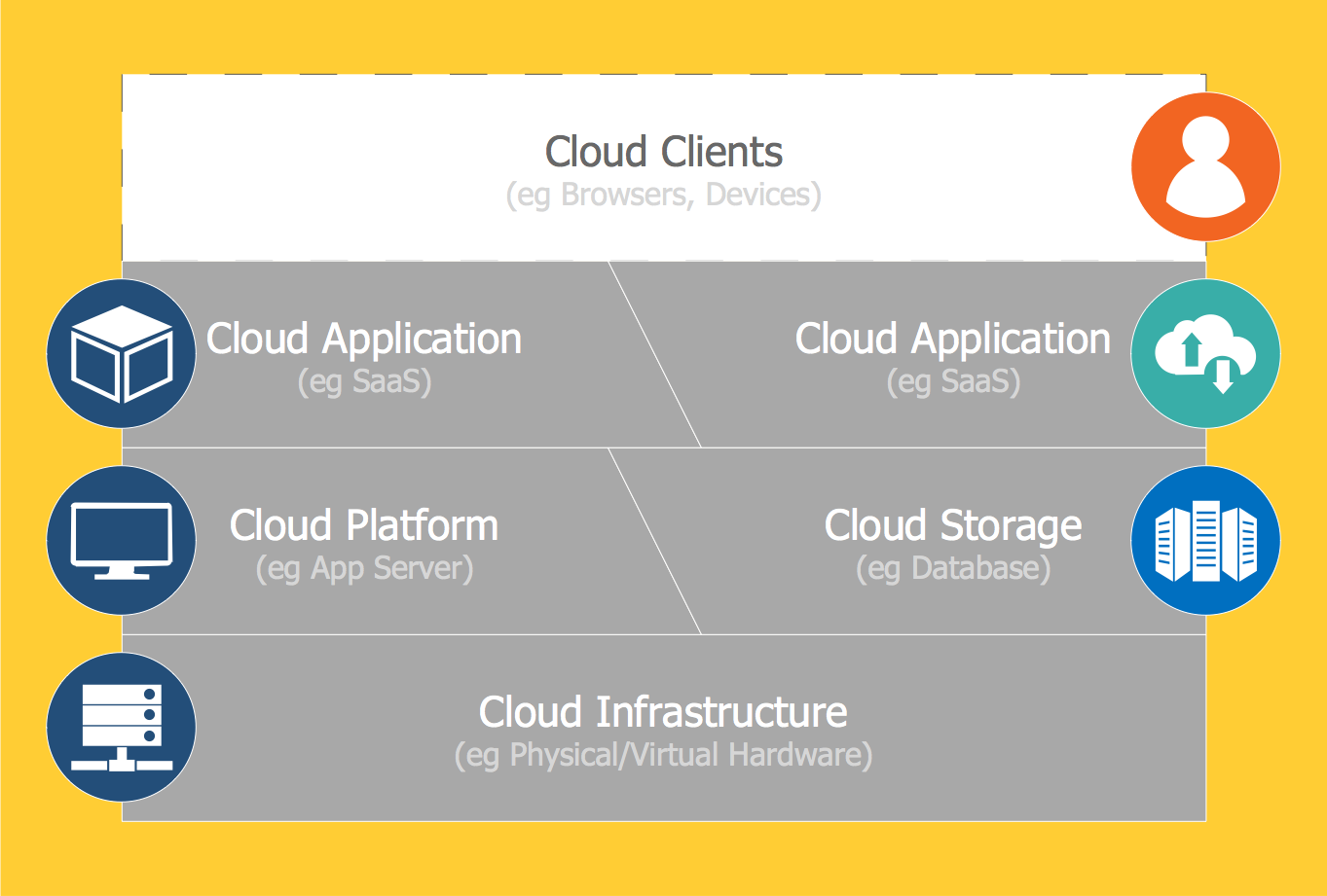
Block Diagram is a technical drawing illustration of a system. Its major parts or components are represented by blocks joined with connection lines to display the relationships between the system parts. The blocks describe a system as a combination of components responsible for specific tasks.
The representation of internal system structure allows a better understanding of the meaningful processes and interconnections between them. It also provides studying the properties of integrated components. Block Diagrams are useful for designing both new processes and existing ones, and also upgrading processes. They are used and play a significant role in a variety of fields.
Block Diagrams are actively used in engineering, electronic design, software design, hardware design, etc. For example, in software development, it is an essential method applied to develop software systems. They are one of the fundamental ways to describe a system, to illustrate a workflow or some process. Electricians, technicians, mechanics, engineers utilize Block Diagrams to describe the systems in the corresponding industry. Being used in electronics, they represent different mechanic systems.
Free Block Diagrams solution included in the "Diagrams" area of the ConceptDraw Solution Park makes ConceptDraw DIAGRAM software the best free Block Diagram maker. Use it to become more creative and productive in visualizing your concepts, ideas, and principles with help of Block Diagrams.
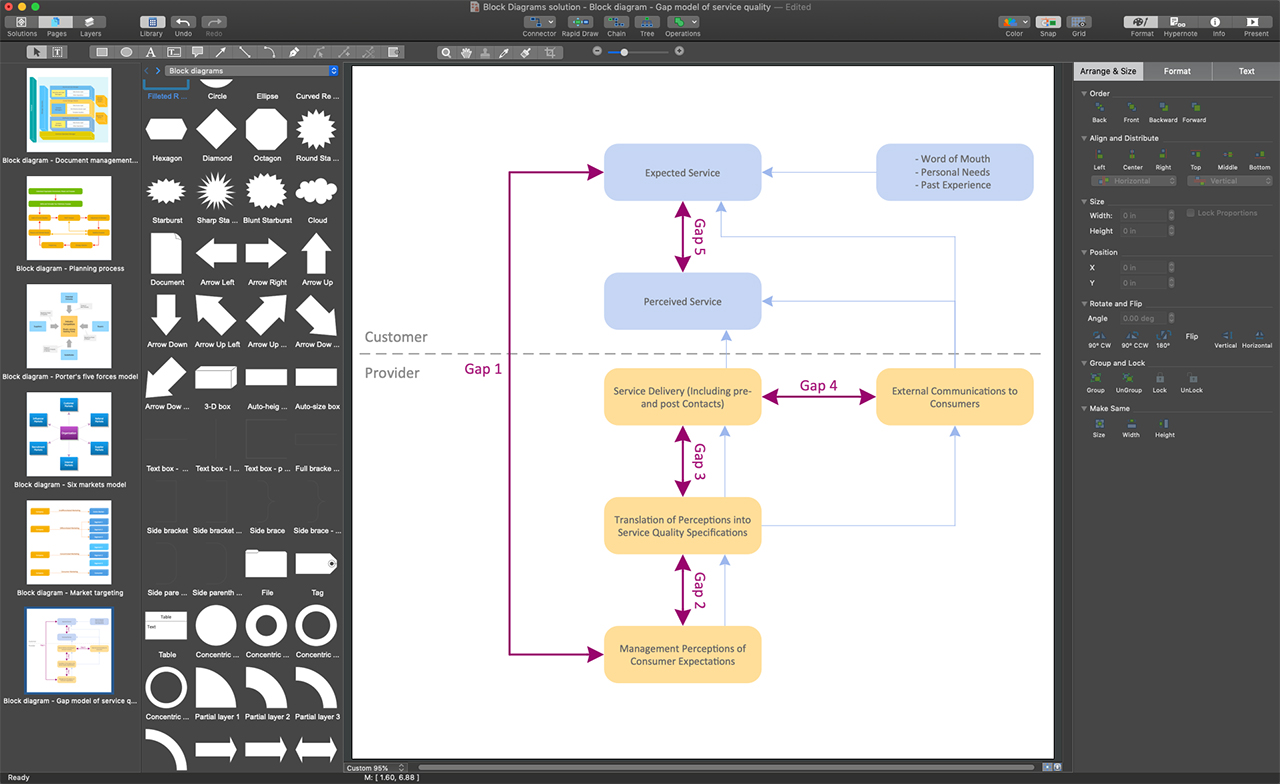
Example 1. ConceptDraw DIAGRAM - Free Block Diagram Maker
Use the professionally designed samples included in the Block Diagrams solution as examples of typical Block Diagrams. You can find here the Gap Model of Service Quality, Six Market Model, Customer Decision Making, and much more diagrams for different industries. Customize any of these examples to design your own unique Block diagram. You also can start with one of the included templates to draw diagrams as quickly as possible. Apply the predesigned vector objects from the large variety of libraries specially prepared and offered at the Block Diagrams solution:
- Block Diagrams library
- Blocks with Perspective library
- Raised Blocks library
- Connectors library
- Callouts library

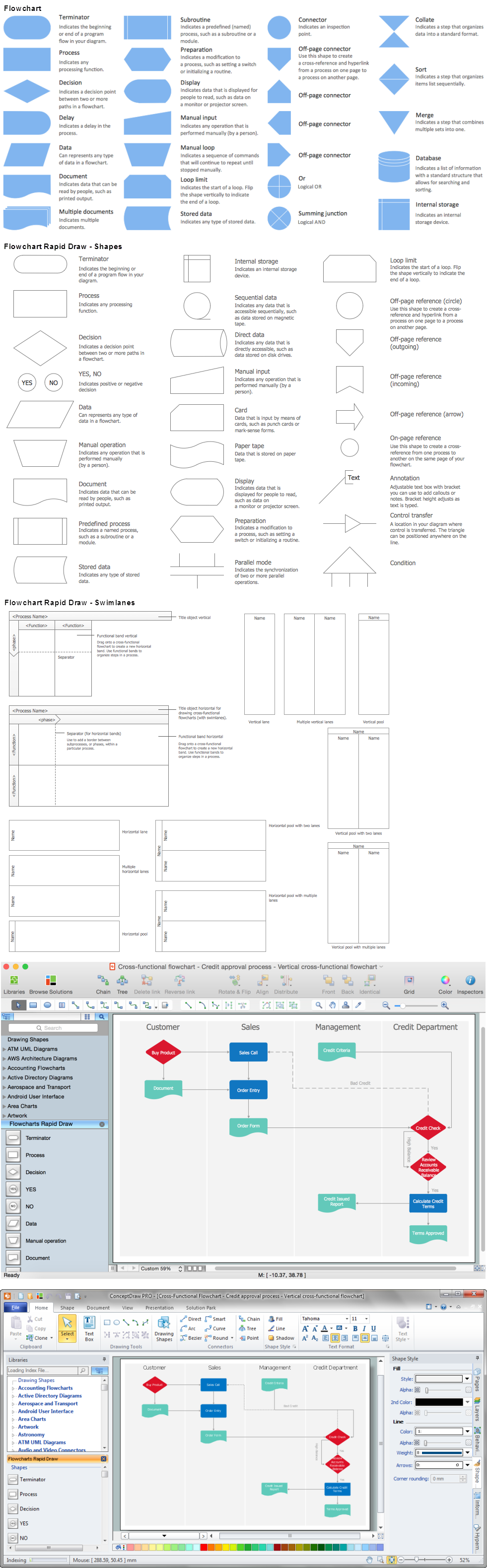
Example 2. Block Diagrams Library Design Elements
The following features make ConceptDraw DIAGRAM the best free Block Diagram maker:
- You don't need to be an artist to draw professional-looking diagrams in a few minutes.
- Large quantity of ready-to-use vector objects makes your drawing diagrams quick and simple.
- Great number of predesigned templates and samples give you a good start for your own diagrams.
- ConceptDraw DIAGRAM provides you the possibility to use the grid, rules, and guides. You can easily rotate, group, align, arrange the objects, use different fonts and colors to make your diagram exceptionally looking.
- All ConceptDraw DIAGRAM documents are vector graphic files and are available for reviewing, modifying, and converting to a variety of formats: image, HTML, PDF file, MS PowerPoint Presentation, Adobe Flash, MS Visio.
- Using ConceptDraw STORE you can navigate through ConceptDraw Solution Park, managing downloads and updates. You can access libraries, templates, and samples directly from the ConceptDraw STORE.
- If you have any questions, our free of charge support is always ready to come to your aid.