Made with
ConceptDraw
DIAGRAM 18

Foreign Policy

Foreign policy or external policy of the state is an activity of the state's government directed on the development of interactions with other states, political entities, and unions. The term "foreign" was introduced in the middle of the 13th century from the French "forain" meaning external, outer, outdoor, remote, not in the own land.

Foreign policy is intended to interact effectively with other countries of the world and protect the national interests of a certain state on the international scene. Moreover, it strives to maximize the benefits of multilateral international cooperation. The concept of national security is an official guiding principle of the foreign policy of many world countries. It includes security in different directions including military security and non-military security like economic security, energy security, and environmental security. Military security is the major way of national security, it supposes the nation's capability to defend itself and deter military aggression.

The state's national security is related to actions of different foreign states and also non-state actors like natural disasters, environmentally detrimental events. The measures and policies taken to ensure national security include using diplomacy, civil defense, emergency preparedness measures, maintaining effective armed forces, using intelligence and counterintelligence services for defense from threats, and many more. Diplomacy is an important part of external policy, it is an art and practice of conduction bilaterally or multilaterally negotiations for developing relationships between states or international organizations, making negotiating alliances, treaties, agreements, etc. Diplomacy is used in issues of economics, trade, culture, peace-making, war, environment, and human rights.

Foreign policy is also directed on the defense of own state's geographical borders, takes care for issues of national, regional, and international security and defense, economy, and politics. Foreign policy develops the set of policies to pursue its national interests as it interacts with other countries including signing treaties and agreements. It has a function to cover a broad range of military, economic, ideological, humanitarian, and political concerns. A foreign policy is influenced by numerous factors like internal state's policies, domestic considerations, behavior and actions of other states, government plans concerning the state's development and advancing specific geopolitical projects.

Foreign Policy

Example 1. Foreign Policy

Today, a country’s foreign policy covers a wide variety of issues including national policy, finance, environmental, cultural, and human rights. It is closely related to economics, trade, travel, and business. The foreign policy of many countries also includes environmental issues, providing aid in disaster relief, or in other issues. Foreign policies of each country consists of strategies based on self-interest, own principles and values, but in considerence with common objectives of interactive states. The principles of foreign policy define the interactions of countries with one another. They include respect for universal values in own country and around the world.

Most countries suppose a significant role of the president and the executive branch including the foreign ministry, defense department, department of homeland security in making and conducting foreign policy. The head of government and foreign minister are responsible for the issues of foreign policy, while legislative and judicial powers have limited influence in this area. Typically, the president has ultimate authority over foreign policy. Public also plays a role in foreign policy.

Foreign Policy Library Design Elements

Example 2. Foreign Policy Library Design Elements

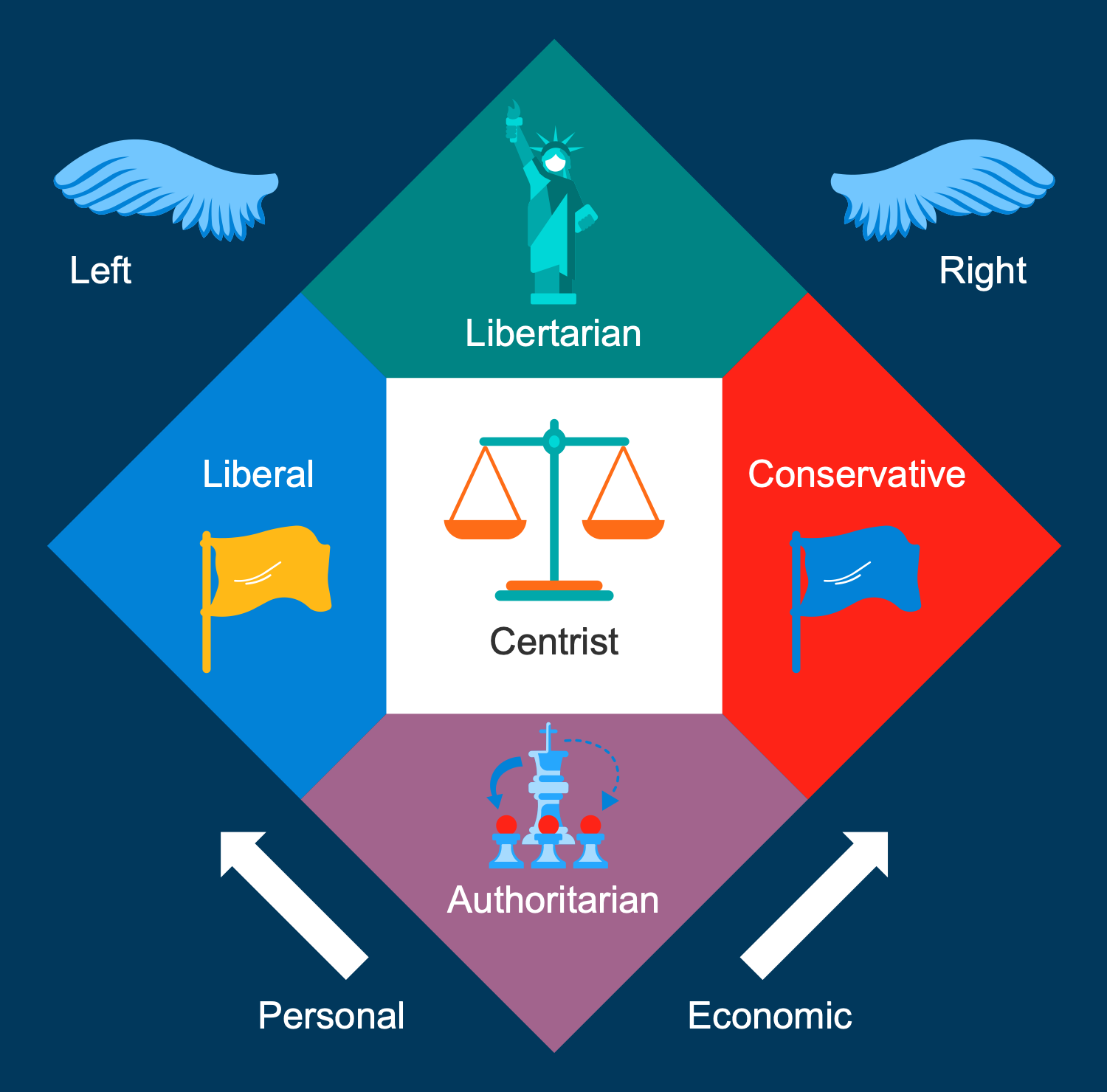
In order to design the best-looking Politics Infographics, to illustrate the key principles and primary goals of the foreign policy of different countries, to compare them visually, use the ConceptDraw DIAGRAM software with powerful Politics Infographics solution. Impress your audience with professional-looking, attractive and interesting content.

Politics Infographics solution with 358 vector design objects and clipart from the political area and a large set of predesigned samples and examples is the best base for your drawing activity. Apply the design elements - foreign policy, civil society, military policy, and many more equally successfully for both personal and professional use.

Politics Infographics Solution - Libraries Design Elements

Example 3. Politics Infographics Solution - Libraries Design Elements

The infographics you see on this page were created in ConceptDraw DIAGRAM software using the Politics Infographics Solution and its pre-made pictograms and clipart. They successfully demonstrate the solution's capabilities and professional results you can achieve. An experienced user spent 10-15 minutes creating each of these samples.

Use the powerful tools of the Politics Infographics Solution for ConceptDraw DIAGRAM software to create your own infographics and diagrams of any complexity fast and easy, and then successfully use them in your work and personal activity.

All source documents are vector graphic documents. They are available for reviewing, modifying, or converting to a variety of formats (PDF file, MS PowerPoint, MS Visio, and many more graphic formats) from the ConceptDraw STORE. The Politics Infographics Solution is available for all ConceptDraw DIAGRAM users.

TEN RELATED HOW TO's:
When trying to figure out the nature of the problems occurring within a project, there are many ways to develop such understanding. One of the most common ways to document processes for further improvement is to draw a process flowchart, which depicts the activities of the process arranged in sequential order — this is business process management. ConceptDraw DIAGRAM is business process mapping software with impressive range of productivity features for business process management and classic project management. This business process management software is helpful for many purposes from different payment processes, or manufacturing processes to chemical processes. Business process mapping flowcharts helps clarify the actual workflow of different people engaged in the same process. This samples were made with ConceptDraw DIAGRAM — business process mapping software for flowcharting and used as classic visio alternative because its briefly named "visio for mac" and for windows, this sort of software named the business process management tools. This flowchart diagram shows a process flow of project management. The diagram that is presented here depicts the project life cycle that is basic for the most of project management methods. Breaking a project into phases allows to track it in the proper manner. Through separation on phases, the total workflow of a project is divided into some foreseeable components, thus making it easier to follow the project status. A project life cycle commonly includes: initiation, definition, design, development and implementation phases. Distinguished method to show parallel and interdependent processes, as well as project life cycle relationships. A flowchart diagram is often used as visual guide to project. For instance, it used by marketing project management software for visualizing stages of marketing activities or as project management workflow tools. Created with ConceptDraw DIAGRAM — business process mapping software which is flowcharting visio alternative or shortly its visio for mac, this sort of software platform often named the business process management tools.Process Flowchart
Picture: Process Flowchart: A Step-by-Step Comprehensive Guide
Related Solution:
Compare flowchart software by type, features, and workflow fit. Learn the difference between desktop and online tools and choose the right solution for documentation or collaboration.Flowchart software feature overview showing templates, symbols, export, collaboration, and layout
Picture: Flowchart Software: Tools for Process and Workflow Diagramming
Related Solution:
A database is a data collection, structured into some conceptual model. Two most common approaches of developing data models are UML diagrams and ER-model diagrams. There are several notations of entity-relationship diagram symbols and their meaning is slightly different. Crow’s Foot notation is quite descriptive and easy to understand, meanwhile, the Chen notation is great for conceptual modeling. An entity relationship diagrams look very simple to a flowcharts. The main difference is the symbols provided by specific ERD notations. There are several models applied in entity-relationship diagrams: conceptual, logical and physical. Creating an entity relationship diagram requires using a specific notation. There are five main components of common ERD notations: Entities, Actions, Attributes, Cardinality and Connections. The two of notations most widely used for creating ERD are Chen notation and Crow foot notation. By the way, the Crow foot notation originates from the Chen notation - it is an adapted version of the Chen notation.ERD Symbols and Meanings
Picture: ERD Symbols and Meanings
Related Solution:
ConceptDraw DIAGRAM - workflow software extended with the Workflow Diagram solution provides a complete set of samples, templates and features help you to draw diagrams faster. A workflow software you use for drawing workflow diagrams and business process flow diagrams should provide a wide set of examples allows you get closer with workflow diagrams, learn symbols meaning, find appropriate layout and design, and then start drawing your own workflow diagram masterfully. Workflow diagrams used for orchestrating organizational processes between company departments and humans, so critical process diagrams used to train many people to interact must be clear and professional to convey an idea from a view. Thats a reason we created a lot workflow symbols and workflow icons collected them into special Workflow Diagram solution in ConceptDraw Solution Park.Workflow Diagram Examples *
Picture: Workflow Diagram Examples
Related Solution:
If you are just a beginner in drawing flowcharts, it may seem that a sheet of paper and a pen are just enough. However, at the time you would want to share your results, diagramming applications would suite you better. it’s very easy to create diagrams that way and to discover new kinds of flowcharts. The huge collection of sample ConceptDraw diagrams, charts, illustrations and other types of business drawings includes a wide range of business themes. A huge number of graphic images of ConceptDraw documents is divides on business application areas according to business-oriented solutions for which they were made.Here is a short visual list of samples of flowcharts, process diagrams, UML models, management charts, computer network diagrams, maps, infographics, illustrations, etc. In short, each ConceptDraw solution is accompanied with at least ten samples representing some particular examples of the application of the given chart.Applications *
Picture: Applications
When thinking about data visualization, one of the first tools that comes to mind is a flowchart design. You can find flowchart symbols, shapes, stencils and icons easily on the Internet, but it might take time to systematize this information. Nevertheless, once you start flowcharting, you’ll love its simplicity and efficiency. This diagram consists from standard flowchart symbols, approved by ANSI (American National Standard Institute) for drawing flowcharts. A flowchart is a diagram that represents a step-by-step algorithm of any process, displaying the process stages as boxes that are connected with arrows. Flowchart design makes it clear and readable. Flowchart designed using ConceptDraw DIAGRAM flowchart software allows to make attractive and clear process presentation, it makes interpretation of the business process flow fresh and versatile. Great flowchart design view is a big advantage over the diagram created manually on a paper.Comparison of bad and good flowchart design showing zigzag flow, crossed connectors, and aligned elements
Picture: Flowchart Design: Principles, Layout, Symbols and Best Practices
Related Solution:
It can be tough to get straight into business papers and processes.Otherwise, you can learn how to create flowcharts for an accounting information system and visualize these documents. Accounting diagrams are clear and easy to understand for all the participants of the process. There are symbols used for creating accounting flowcharts using ConceptDraw DIAGRAM and its Accounting Flowcharts solution. Accounting flow charts are a special kind of flow charts. Actually a variety of flowcharts are often used to facilitate many aspects of a workflow of accounting department. Accounting flowcharts are utilized to support creating accounting documentation, to depict positions responsible for fulfillment of each phase of accounting workflow.How to Create Flowcharts for an Accounting Information System
Picture:
How to Create Flowcharts for an
Accounting Information System
Related Solution:
A flowchart is a powerful tool for examining processes. It helps improving processes a lot, as it becomes much easier to communicate between involved people, to identify potential problems and to optimize workflow. There are flowcharts of different shapes, sizes and types of flowchart vary from quite basic process flowcharts to complex program flowcharts. Nevertheless, all these diagrams use the same set of special symbols like arrows to connect blocks, parallelogram to show data receiving or rectangles for showing process steps. Basic flowcharts are used to represent a simple process algorithm. A basic flowchart notation consists of rectangles (business processes), arrows (the flow of information, documents, etc.). The same notation is used in items such as the "decision", which allow you to do the branching. To indicate the start of the entire business process and its termination can be used the "Terminator" element. The advantages of Basic Flowchart are simplicity and clarity. With it you can quickly describe the business process steps. Creating of Basic Flowchart does not require any special knowledge, as easily understand by employees with different levels of education and IQ.Types of Flowchart — Overview
Picture: Types of Flowchart: Comprehensive Overview
Related Solution:
There are many ways to track the system in a critical situation. To model a system behavior, uml notation is widely used. Usually, an UML diagram consists of elements such as actor and a case. This diagram represents the structure of UML notations. Unified Modeling Language (UML) is used in software engineering to depict graphically the software modeling process. UM Language uses graphic notations for developing models of object-oriented systems. These notations displays requirements, sub-systems, logical and physical elements, etc. We created this diagram using ConceptDraw DIAGRAM reinforced with Rapid UML solution. It can be helpful for students on software engineering, when learning UML.UML Notation *
Picture: UML Notation
Related Solution:
Local area network connects computers and other network appliances within an area, such as office building or a campus. It can be difficult to provide such network without a predesigned plan. For these purposes you can use network diagram software, which helps you to create LAN network diagrams and office network diagrams quickly and effortless. This will speed up your work and you can save the diagram for the future network improvements. The following diagram illustrates a network topology of the small office. LAN configuration has a star topology. The local network joins 8 computers among which are several desktop PCs, laptop, two iMacs and iBook. The end-point devices are divided into three groups. Each group is connected to its hub. There is a network printer and a modem, which are interconnected with other devices through a network server. Each computer on the LAN can access the server through a corresponding hub.LAN Network Diagram
Picture: Network Diagram Software. LAN Network Diagrams. Physical Office Network Diagrams
Related Solution:
ConceptDraw
DIAGRAM 18