Electrical Symbol
Electricity is an essential part of our life, but however, it is an incredibly complex system offering great benefits and concealing full of dangers. Electrical safety is the most important issue, therefore it is incredibly important to treat with consideration and seriousness the development and implementation of electrical schematics and diagrams, and the further use and maintenance of electrical equipment. It is also important to comply with the generally accepted rules and standards, and use standardized pictograms, symbols, and signs of electrical components and hazards and safety signs when designing electrical schematics.
The electronic circuit shows a combination of electronic components and how they are interconnected to flow the electric current. To show the circuit nodes the electrical symbols are used in electrical schematics, circuits, and diagrams. These are generally accepted and internationally standardized pictograms, symbols, and signs by the IEEE 315 standard or the British 3939 standard. They show various electrical and electronic devices and components of electrical circuits like transformers, switches, batteries, resistors, diodes, inductors, logic gates, capacitors, antennas, transistors, wires, etc. The use of lines, dots, letters, and numbers uniquely identifies an electrical symbol. Some symbols are identical in different standards. The diagram may also include codes for specific components and reference designators. The use of standardized electrical symbols makes electrical diagrams clear for everyone and helps avoid mistakes and confusion. The inclusion of a legend accompanying a diagram is a benefit for readers to clarify the meaning of the used electrical symbols.
The diagram with electrical symbols conveys a clear visual overview for electrical engineers, electricians, overhead lines staff, and other stakeholders to build, repair, and maintain an electrical system. It helps to detect equipment location and realize easily the rearrangement of components if it is necessary. These diagrams are an integral part of technical documentation, reports, patents, instructions, and other documentation accompanying electronic and electrical products. Electrical diagrams and schematics with electrical symbols are also used in educational process and research, to develop and describe electrical systems, explore possible problems and ways to solve them, and many more tasks.
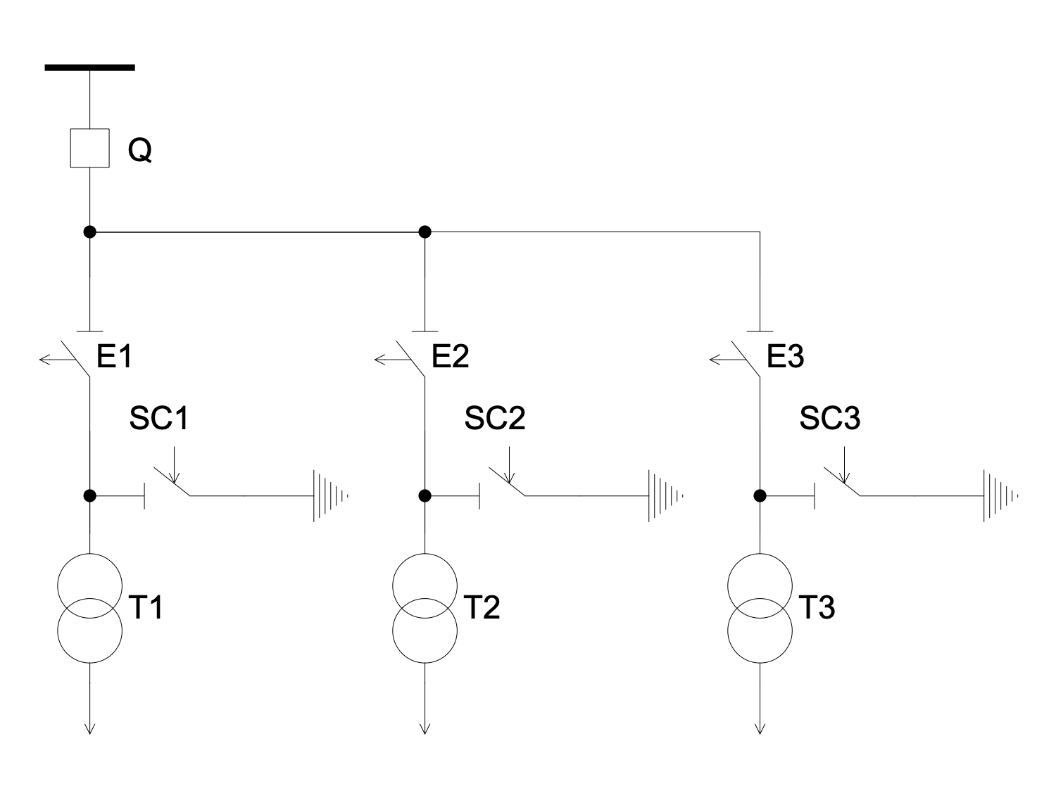
Example 1. Electrical Symbol in One-line Diagram
ConceptDraw DIAGRAM software with the One-line Diagrams solution offers plenty of libraries with predesigned vector technical and engineering electrical symbols for the intuitive drawing of Electrical circuits, One-line diagrams, and Electrical Schematics. 4 libraries of vector stencils including transformers, generators, switches, transistors, resistors, circuit breakers, and other elements simplify creating of any kinds of Electrical engineering and One-line diagrams.

Example 2. One-line Diagrams Solution Libraries Design Elements
A collection of ready samples is also included in One-line Diagrams solution and you can use any of them to create your diagram based on it or make your drawings from scratch. It includes Differential protection circuit, Ring bar configuration, Low power electricity meter, Electric substation without high voltage switchgear, Monopolar HVDC, and many more samples. Adding the dimensions and legend to your diagram is also possible.

Example 3. One-Line Diagram — FACTS Shunt Compensation
The One-line Diagram samples you see on this page were created in ConceptDraw DIAGRAM software using the drawing tools of the One-line Diagrams Solution. These examples successfully demonstrate the solution's capabilities and the professional results you can achieve using it. An experienced user spent 5-15 minutes creating each of these samples.
Use the drawing tools of the One-line Diagrams solution to design your own Single-line diagrams and schematics quick, easy, and effective.
All source documents are vector graphic documents. They are available for reviewing, modifying, or converting to a variety of formats (PDF file, MS PowerPoint, MS Visio, and many other graphic formats) from the ConceptDraw STORE. The One-line Diagrams Solution is available for ConceptDraw DIAGRAM users.