Diode Symbols
A diode is a semiconductor device that conducts electric current in only one direction. The flowing of current in the opposite direction is blocked. This is a two-terminal electrical component including two distinct electrodes (a negatively charged cathode and a positively charged anode), therefore it is called a diode. The current flows from the anode to the cathode. The first diodes were constructed as vacuum tubes from glass or metal, evacuated or filled with a pure elemental gas at low pressure. Currently, most diodes are made with semiconductor materials (selenium, silicon, germanium). Diodes have a wide application. They are used in many electronic devices, radio and television electronic circuits, detectors, temperature sensors, for demodulation in radio receivers. Being used as converters or rectifiers, they convert alternating current (AC) into direct current (DC). The light-emitting diodes are often used as status indicators in electronic devices.
The diode can operate as a switch, a one-way valve for an electrical circuit, signal limiter, voltage regulator, or an insulator that permits current to flow exceptionally in one direction. Diodes are also used as signal mixers, signal modulators, signal demodulators, or oscillators. The diode has a minor resistance in one direction that allows current to flow and high resistance in the reverse direction to prevent current flow. Ideally, it needs to have zero resistance in one direction and infinite in the reverse direction, however in reality it is not achieved.
Diodes are available in various configurations, can have various types, voltage, and current capacity. The most common type are semiconductor diodes. The PN junction is their simplest form, an N-type semiconductor (negatively charged cathode) is joined with a P-type semiconductor (positively charged anode). If the positive side of a voltage source is connected to the anode and the negative side is respectively connected to the cathode, the diode will conduct current. And the current will be blocked if the diode is reversed.
Example 1. Diode Symbols in Circuit Diagrams
One differs forward-biased and reverse-biased diodes. The diodes are forward-biased when the voltage across a diode permits the natural flow of current. In the opposite case, at the conducting current in the opposite direction, we tell about the reverse-biased. Zener diodes are an example of reverse-biased diodes. The forward-biased PN junction behaves as a short circuit and respectively as an open circuit being reverse-biased. Light-emitting diodes (LEDs), commonly used in electronic and computer equipment, are also PN junctions. They emit visible light or IR energy when a current passes through them.
The connection of several diodes in series allows the development of a rectifier that converts AC to DC. The photovoltaic cells used in solar electric energy systems and photosensors are also semiconductor diodes, which produce DC when visible light, ultraviolet (UV), or infrared transmission (IR) energy falls on them. The varactor diodes are used in the radio and television for signal transmission, the change of the bias voltage causes a variation in the diode capacitance.

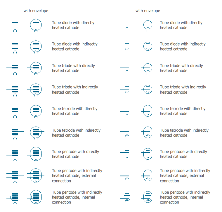
Example 2. Vacuum Tubes IEC - Design Elements
ConceptDraw DIAGRAM software extended with the Electron Tube Circuits solution is ideal for electrical engineering design. It includes a variety of pre-made samples and a collection of predesigned vector symbols and clipart, including the diode symbol among the design elements — Vacuum Tubes IEC library. All included elements are vector, resizable and perfect for easy creating electrical circuits.

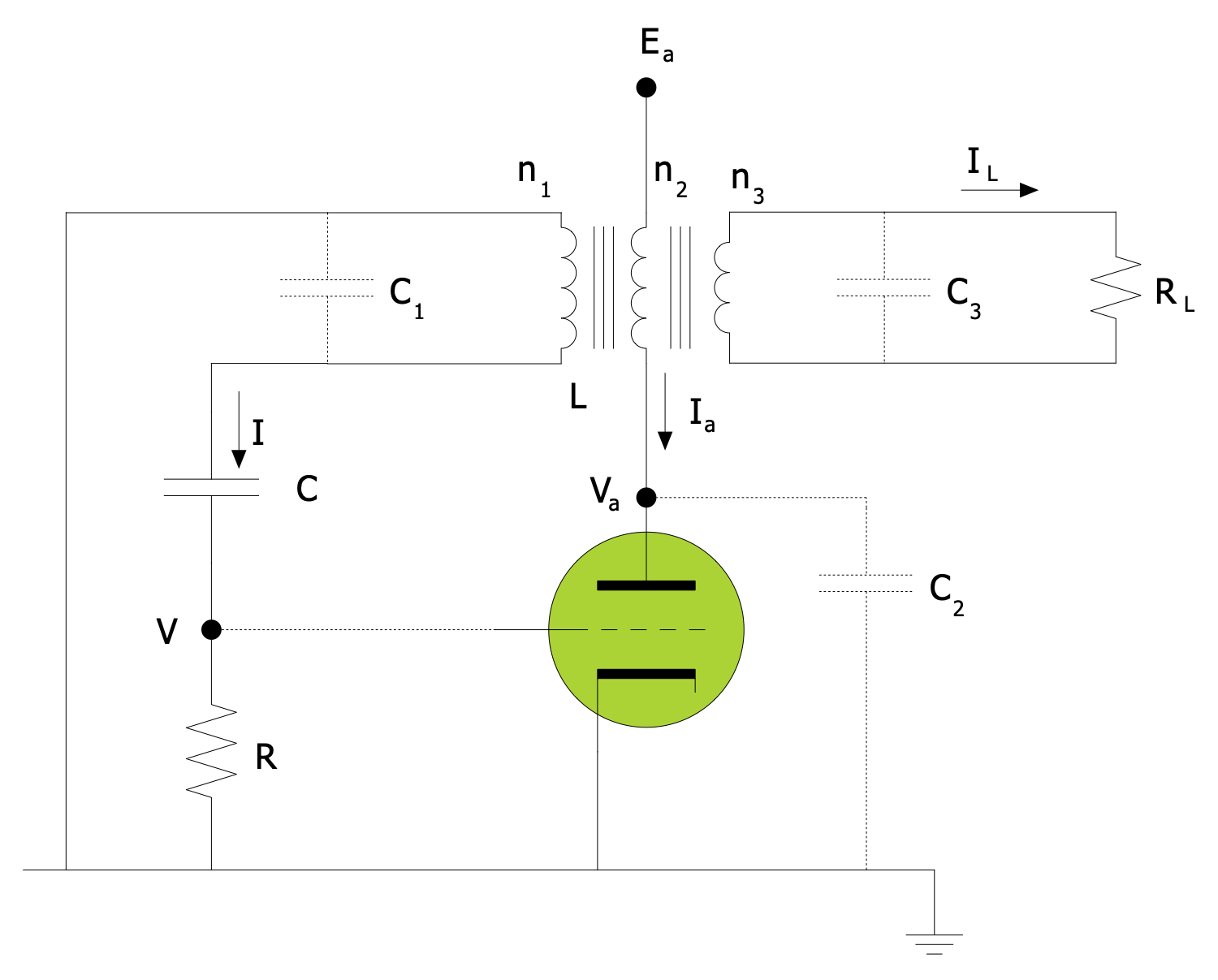
Example 3. Audion Circuit
The Electron Tube Circuits samples you see on this page were created in ConceptDraw DIAGRAM software using the drawing tools of the Electron Tube Circuits Solution. These examples successfully demonstrate the solution's capabilities and professional results you can achieve using it. An experienced user spent 5-10 minutes creating each of these samples.
Use the drawing tools of the Electron Tube Circuits solution to design your own Electron Tube Circuits Infographics quick, easy, and effective.
All source documents are vector graphic documents. They are available for reviewing, modifying, or converting to a variety of formats (PDF file, MS PowerPoint, MS Visio, and many other graphic formats) from the ConceptDraw STORE. The Electron Tube Circuits Solution is available for ConceptDraw DIAGRAM users.