3 Way Switch Diagram
Different kinds of switches are used to control light fixtures in buildings. A single pole switch is the most common type of switches but allows controlling a light only from one location in the premise. To control lighting from two or more locations, 3-way switches and 4-way switches are used.
What is the Actual 3-way Switch?
A 3-way switch is a single pole double throw switch (SPDT) that allows controlling light or an electrical fixture from two separate locations. It's convenient to turn the light on when you are, for example, on one side of a hallway or stairs and to turn it off when passing the opposite side. Therefore 3-way switches are often installed at the different ends of a hallway or a room, or at the top and bottom of a stairway, near multiple doorways into a large room. Both switches are equal in functionality and are used to turn lights on/off with any of them. To increase the number of control locations, the combination of 3-way switches with 4-way switches is used.
How is a 3-way Switch Wiring?
When both switches are up or down, the circuit is complete and the light turns on, while if the switches are in opposite directions, the circuit is open and the light is off. The pair of switches is connected by three wires, one of which is a common wire to communicate with each other. Typically, two terminals of a 3-way switch have the same color and the third common terminal has a different color. Toggling one of two connected 3-way switches changes the state of the load from on to off and vice versa.
The modern 3-way switches have four screw terminals, which earlier didn't use in switches. A green grounding screw is connected to the bare copper or green insulated ground wire. The travel wires are connected to two lighter screws of brass color and offer two pathways to pass power from one switch to the other. Toggling the switch disconnects one travel terminal and connects the other one. The white wire coming straight from the power source always goes uninterrupted into the light fixture. And the last screw is a common terminal from dark brass, copper, or black, which connects the hot or charged (usually black) wire from the power source and the hot wire that leads to the light fixture. The hot wire always routes through the switch, which interrupts the hot wire when is turned off.
There are three basic ways in which three-way switches may be set up to control one or more lights:
- The wires from the power source enter one switch box, then travel to the light, and terminate at the other switch.
- The wires from the power source enter the light fixture box, travel to one switch, and then connect that switch to the other switch.
- The wires from the power source go from one switch to the second and then to the light fixture.
When more than two switches are used, the add of one or more 4-way switches is necessary between the 3-way switches. A 4-way switch has two positions: when the contacts are connected straight through and when the contacts on the left are switched cross with the contacts on the right. 3 way switch diagram aptly shows how the switches are installed and set up in a circuit.
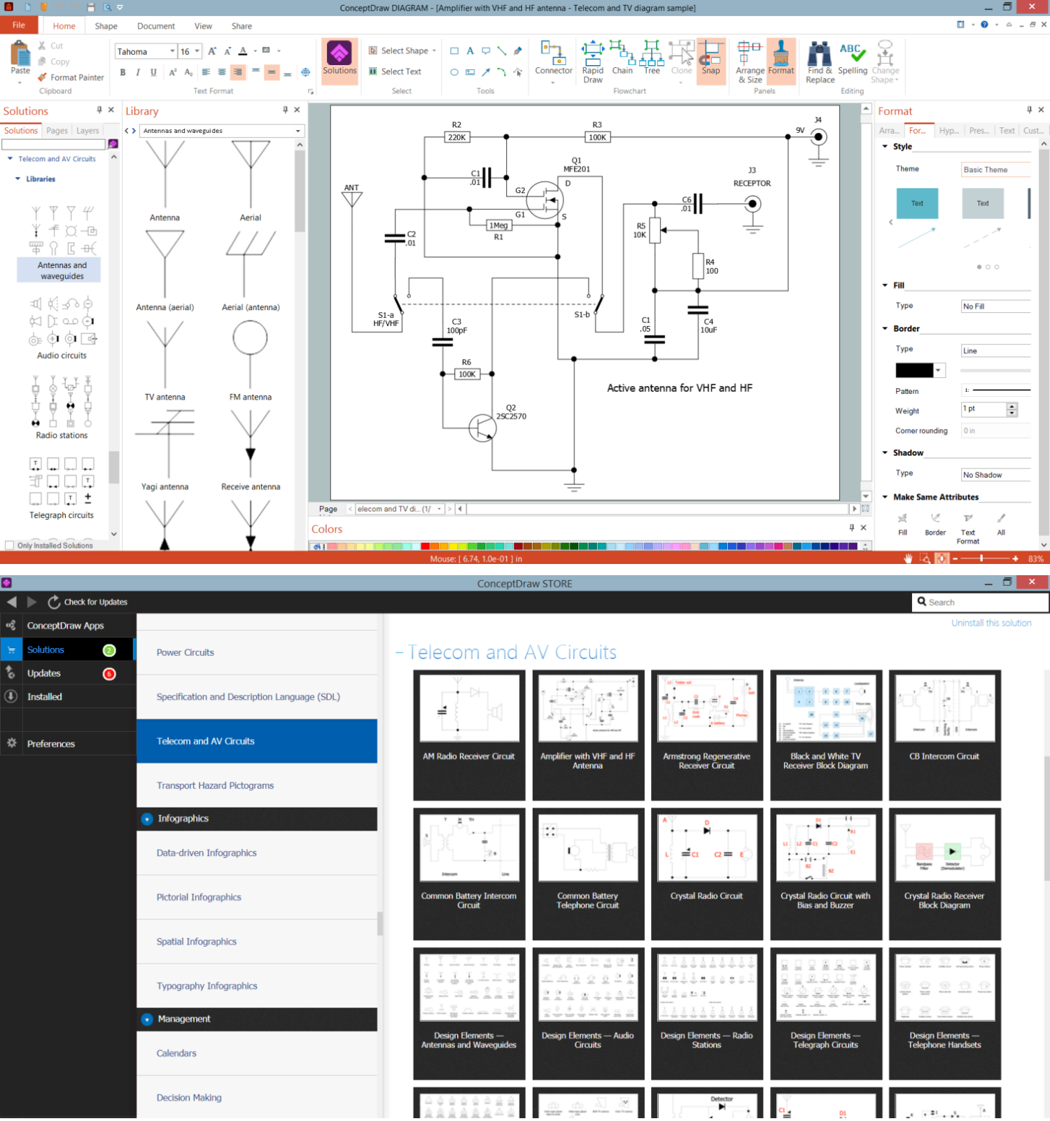
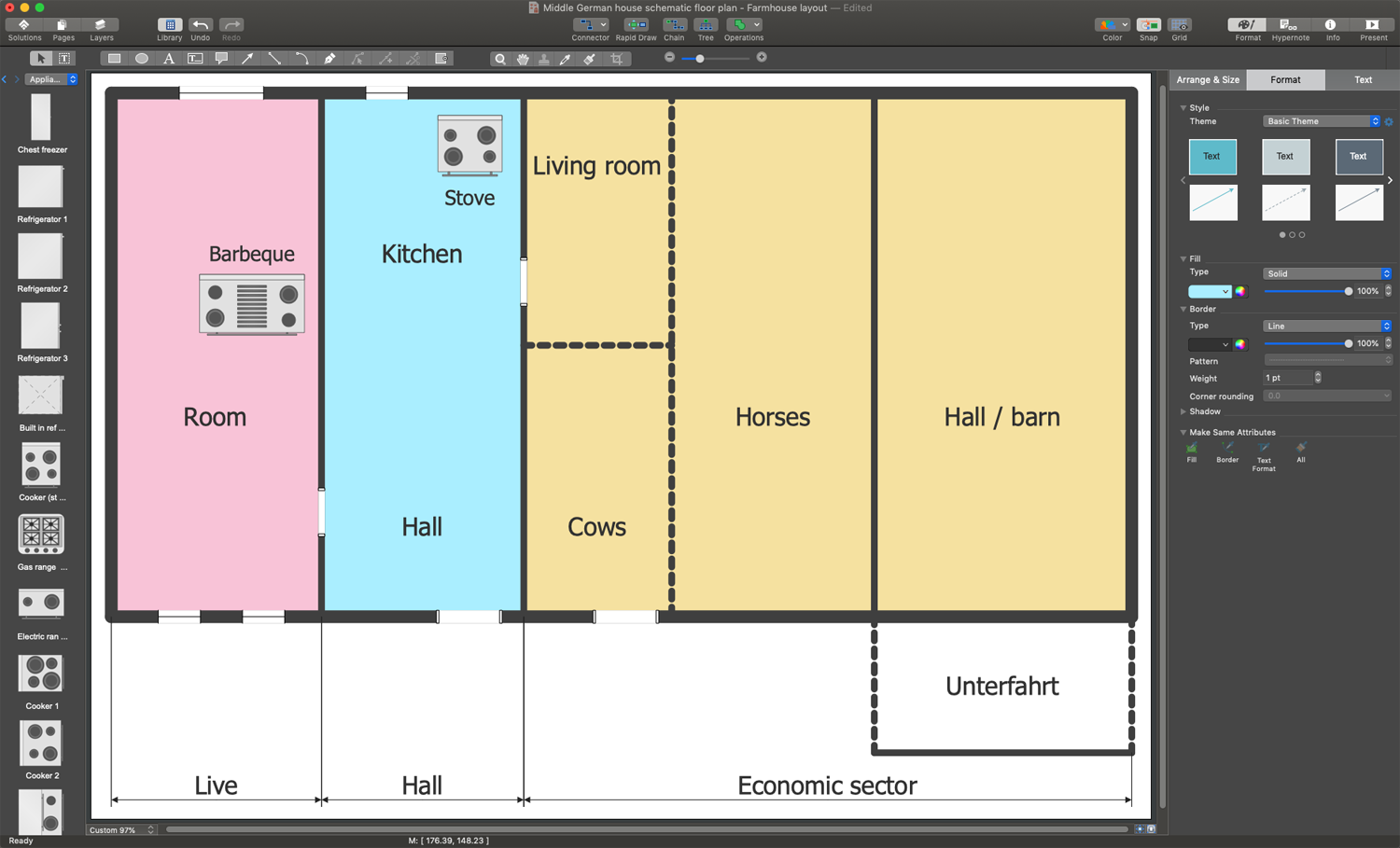
Example 1. 3 Way Switch Diagram in ConceptDraw DIAGRAM
The easiest way to design effectively 3 way switch diagrams and other kinds of telecom and AV circuits and infographics is to use the powerful tools of Telecom and AV Circuits solution for ConceptDraw DIAGRAM software. It includes a large collection of samples including radio circuits, telephone circuits, telephone circuits, radio receivers diagrams, amplifier with VHF and HF antenna, and many more. 7 libraries of vector design elements included to Telecom and AV Circuits solution are helpful to create a diagram of any complexity in minutes:
- Antennas and Waveguides
- Audio Circuits
- Radio Stations
- Telegraph Circuits
- Telephone Handsets
- VHF, UHF, SHF
- Video and TV Circuits

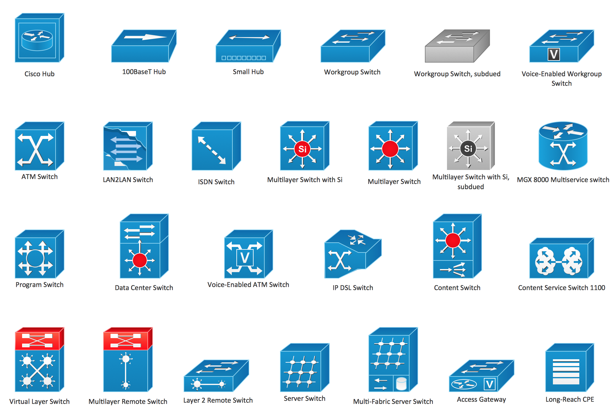
Example 3. VHF, UHF, SHF Library Design Elements
The Telecom and AV Circuits samples you see on this page were created in ConceptDraw DIAGRAM software using the drawing tools of the Telecom and AV Circuits Solution. These examples successfully demonstrate the solution's capabilities and the professional results you can achieve using it. An experienced user spent 5-10 minutes creating each of these samples.
Use the drawing tools of the Telecom and AV Circuits solution to design your own Telecom and AV Circuits diagrams and infographics quick, easy, and effective.
All source documents are vector graphic documents. They are available for reviewing, modifying, or converting to a variety of formats (PDF file, MS PowerPoint, MS Visio, and many other graphic formats) from the ConceptDraw STORE. The Telecom and AV Circuits Solution is available for ConceptDraw DIAGRAM users.