HelpDesk
How to Create an Electrical Diagram Using ConceptDraw PRO
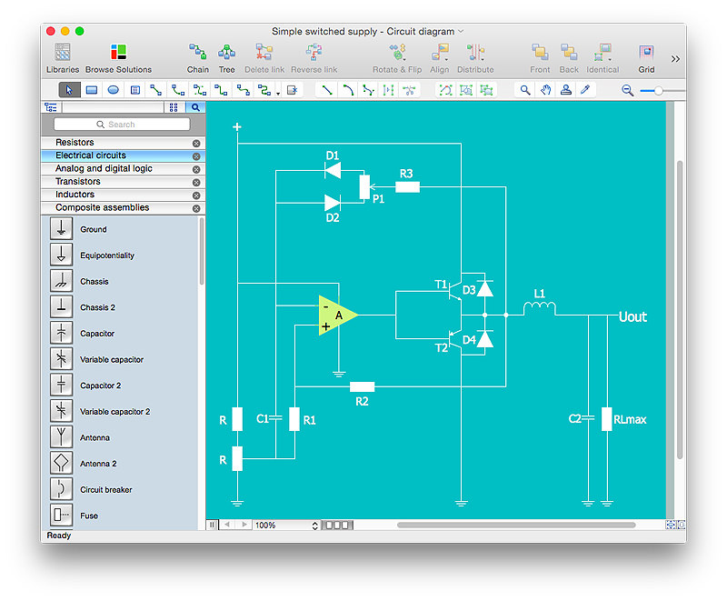
There are many of different electric circuit symbols that can be used in a circuit diagram. Knowing how to read circuit diagrams is a useful skill not only for professionals, but for any person who can start creating his own small home electronic projects. The circuit diagram shows the scheme of a location of components and connections of the electrical circuit using a set of standard symbols. It can be use for graphical documentation of an electrical circuit components. The ability to create electrical diagrams and schematic using ConceptDraw PRO is delivered by the Electrical Engineering solution. The solution supplied with samples, templates and libraries of design elements for drawing electrical schematics, digital and analog logic, circuit and wiring schematics and diagrams, power systems diagrams, maintenance and repair diagrams for electronics and electrical engineering.HelpDesk
How to Draw an Electrical Scheme Using ConceptDraw Solution Park
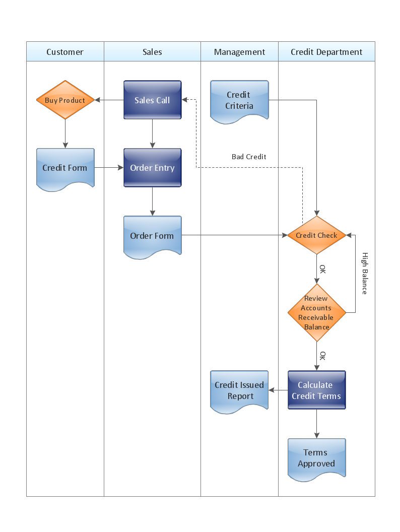
The ability to visualize industrial systems in electronics, electrical, chemical, process, and mechanical engineering is delivered by the ConceptDraw Engineering solution.Cross-Functional Flowchart - The easiest way to draw crossfunctional
ConceptDraw PRO diagramming software provides vector shapes and connector tools for quick and easy drawing diagrams for business, technology, science and education. Use ConceptDraw PRO enhanced with solutions from ConceptDraw Solution Park to create diagrams to present and explain structures, process flows, logical relationships, networks, design schemes and other visually organized information and knowledge.
 ConceptDraw Solution Park
ConceptDraw Solution Park collects graphic extensions, examples and learning materials
- Flowchart Of Electricity Bill Payment
- Accounting Flowcharts | Flowchart Of Electric Bill
- Electrical Drawing Software and Electrical Symbols | Swim Lane ...
- Model Based Systems Engineering | DFD Library System | Electrical ...
- Types of Flowcharts | Electrical Drawing Software and Electrical ...
- Flow chart Example. Warehouse Flowchart | Building Drawing ...
- Electrical Drawing Software and Electrical Symbols | Electrical ...
- How To Draw Flowchart Of Electricity Bill Payment
- Process Flowchart | How To use House Electrical Plan Software ...
- Flowchart Of Basic Elements Of Electronics
- Cross-Functional Flowcharts | How To Draw Building Plans | Event ...
- Draw A Flow Chart Of Earth Movement
- Electrical Drawing Software and Electrical Symbols | Wiring ...
- Flowchart Of Basic Element Of Electronic
- Flowchart Of Computer Aided Design
- Prepare Flow Chart Of Sound Symbols
- Flowchart Examples and Templates | How to Draw an Electrical ...
- How To Draw Flowchart Of Frequency Meter
- Bar Graphs | Kids Flowchart Of Basic Functions Of Computer
- Process Flowchart | Electrical Drawing Software and Electrical ...


