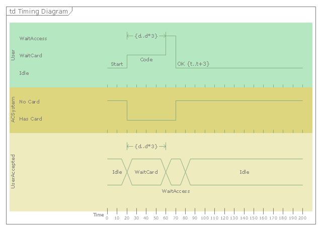
"A timing diagram in the Unified Modeling Language 2.0 is a specific type of interaction diagram, where the focus is on timing constraints.
Timing diagrams are used to explore the behaviors of objects throughout a given period of time. A timing diagram is a special form of a sequence diagram. The differences between timing diagram and sequence diagram are the axes are reversed so that the time is increased from left to right and the lifelines are shown in separate compartments arranged vertically.
There are two basic flavors of timing diagram: the concise notation, and the robust notation." [Timing diagram (Unified Modeling Language). Wikipedia]
This UML timing diagram example was created using the ConceptDraw PRO diagramming and vector drawing software extended with the Rapid UML solution from the Software Development area of ConceptDraw Solution Park.
UML timing diagram
"A deployment diagram in the Unified Modeling Language models the physical deployment of artifacts on nodes. To describe a web site, for example, a deployment diagram would show what hardware components ("nodes") exist (e.g., a web server, an application server, and a database server), what software components ("artifacts") run on each node (e.g., web application, database), and how the different pieces are connected (e.g. JDBC, REST, RMI)." [Deployment diagram. Wikipedia]
This UML deployment diagram example was created using the ConceptDraw PRO diagramming and vector drawing software extended with the Rapid UML solution from the Software Development area of ConceptDraw Solution Park.
This UML deployment diagram example was created using the ConceptDraw PRO diagramming and vector drawing software extended with the Rapid UML solution from the Software Development area of ConceptDraw Solution Park.
UML deployment diagram

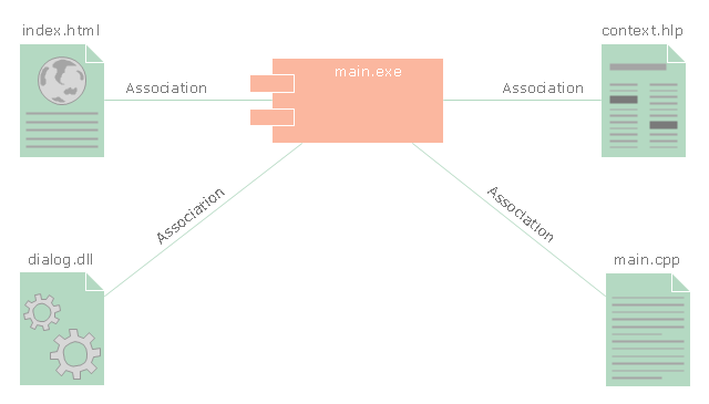
"In the Unified Modeling Language, a component diagram depicts how components are wired together to form larger components and or software systems. They are used to illustrate the structure of arbitrarily complex systems." [Component diagram. Wikipedia]
This UML component diagram example was created using the ConceptDraw PRO diagramming and vector drawing software extended with the Rapid UML solution from the Software Development area of ConceptDraw Solution Park.
This UML component diagram example was created using the ConceptDraw PRO diagramming and vector drawing software extended with the Rapid UML solution from the Software Development area of ConceptDraw Solution Park.
UML component diagram
- Unified Modeling Language Diagram | UML Diagram | Venn ...
- Unified Modeling Language Diagram | UML Diagram | Design ...
- UML Diagram | Unified Modeling Language Diagram | ConceptDraw ...
- UML Diagram | Unified Modeling Language Diagram | Design ...
- Unified Modeling Language Diagram | UML Diagram | SYSML ...
- UML Diagram | Unified Modeling Language Diagram | Design ...
- UML Diagram | Unified Modeling Language Diagram | UML ...
- Unified Modeling Language Tools Example
- UML Diagram | Unified Modeling Language Diagram | Express-G ...
- Unified Modeling Language Tools And Techniques
- UML Sequence Diagram Example . SVG Vectored UML Diagrams ...
- Modeling Uml
- Design elements - ERD (crow's foot notation) | UML Notation ...
- ORM Diagram | Unified Modeling Language Tutorial
- Uml Is A General Purpose Modeling Language In The Field Of
- Type Of Uml Diagrams
- UML Diagram | Design Elements for UML Diagrams | UML Business ...
- UML Diagrams with ConceptDraw PRO | UML Diagram | Business ...
- UML Sample Project | UML Use Case Diagram Example Social ...
- UML Tool & UML Diagram Examples | UML Diagram Types List ...