HelpDesk
How to Draw a Chemical Process Flow Diagram

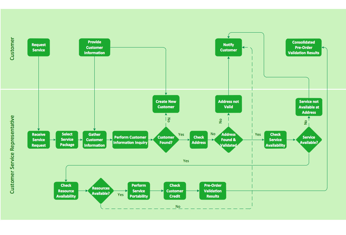
Cross-functional flowchart landscape, U.S. units
- Process Flow Diagram Symbols | Process Flowchart | Types of ...
- 5 Types Of Chemical Reaction Flow Chart Genral Symbolic Reaction
- Types Of Chemical Engineering Flow Sheet
- Process Flow Types In Chemical Engineering
- Process Engineering | Process Diagrams | Process Flowchart | Type ...
- Chemical Industries Flow Chart
- Process Flowchart | Process Engineering | Types of Flowcharts ...
- Chemical and Process Engineering | How to Draw a Chemical ...
- Process Flowchart | Types of Flowcharts | Process Flow Diagram ...
- Process Flowchart | Types of Flowcharts | How to Draw a Chemical ...
- The Three Types Of Flow Sheet Applicable In Chemical Engineering
- How to Draw a Chemical Process Flow Diagram
- Type Of Flow Diagram From Chemical Plant
- Process Flow Diagram Symbols | Process Flowchart | How to Draw a ...
- Natural gas condensate - PFD | Types of Flowcharts | Process Flow ...
- Types of Flowcharts | Process Flowchart | Process Flow Diagram ...
- Process Flowchart | How to Draw a Chemical Process Flow Diagram ...
- Process flow diagram - Typical oil refinery | Types of Flowcharts ...
- Process Flowchart | Process Flow Diagram Symbols | How to Draw a ...
- Process Flowchart | Process Flow Diagram Symbols | Types of ...