HelpDesk
How to Create Flowchart Using Standard Flowchart Symbols

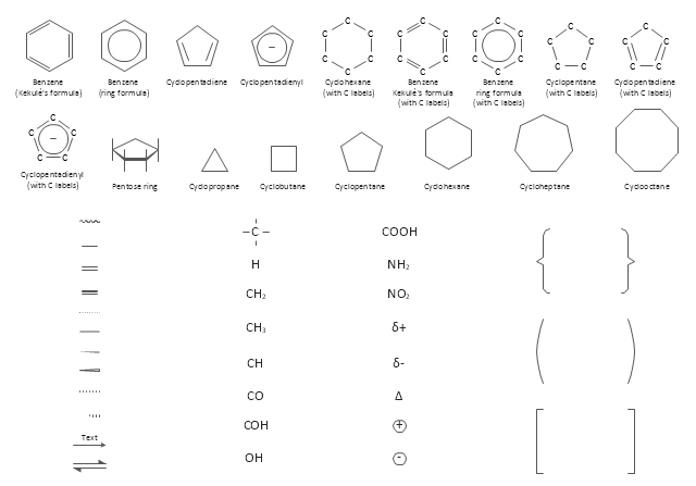
The vector stencils library "Chemical drawings" contains 81 symbols of organic compounds and functional groups for chemical drawing.
Use it to draw structural formulas of organic molecules, schemes of chemical reactions and organic chemistry diagrams.
"Structural drawings.
Organic molecules are described more commonly by drawings or structural formulas, combinations of drawings and chemical symbols. The line-angle formula is simple and unambiguous. In this system, the endpoints and intersections of each line represent one carbon, and hydrogen atoms can either be notated explicitly or assumed to be present as implied by tetravalent carbon. The depiction of organic compounds with drawings is greatly simplified by the fact that carbon in almost all organic compounds has four bonds, nitrogen three, oxygen two, and hydrogen one. ...
Organic reactions.
Organic reactions are chemical reactions involving organic compounds. While pure hydrocarbons undergo certain limited classes of reactions, many more reactions which organic compounds undergo are largely determined by functional groups. The general theory of these reactions involves careful analysis of such properties as the electron affinity of key atoms, bond strengths and steric hindrance. These issues can determine the relative stability of short-lived reactive intermediates, which usually directly determine the path of the reaction.
The basic reaction types are: addition reactions, elimination reactions, substitution reactions, pericyclic reactions, rearrangement reactions and redox reactions. ...
Each reaction has a stepwise reaction mechanism that explains how it happens in sequence - although the detailed description of steps is not always clear from a list of reactants alone.
The stepwise course of any given reaction mechanism can be represented using arrow pushing techniques in which curved arrows are used to track the movement of electrons as starting materials transition through intermediates to final products." [Organic chemistry. Wikipedia]
The chemical symbols example "Design elements - Chemical drawings" was created using the ConceptDraw PRO software extended with the Chemistry solution from the Science and Education area of ConceptDraw Solution Park.
Chemical symbols
"The symbols and conventions used in welding documentation are specified in national and international standards such as ISO 2553 Welded, brazed and soldered joints -- Symbolic representation on drawings and ISO 4063 Welding and allied processes -- Nomenclature of processes and reference numbers. The US standard symbols are outlined by the American National Standards Institute and the American Welding Society and are noted as "ANSI/ AWS".
In engineering drawings, each weld is conventionally identified by an arrow which points to the joint to be welded. The arrow is annotated with letters, numbers and symbols which indicate the exact specification of the weld. In complex applications, such as those involving alloys other than mild steel, more information may be called for than can comfortably be indicated using the symbols alone. Annotations are used in these cases." [Symbols and conventions used in welding documentation. Wikipedia]
The example chart "Elements of welding symbol" is redesigned using the ConceptDraw PRO diagramming and vector drawing software from the Wikipedia file: Elements of a welding symbol.PNG.
[en.wikipedia.org/ wiki/ File:Elements_ of_ a_ welding_ symbol.PNG]
The diagram example "Elements location of a welding symbol" is contained in the Mechanical Engineering solution from the Engineering area of ConceptDraw Solution Park.
Welding joint symbol chart

- Data Flow Diagram Symbols . DFD Library | Entity Relationship ...
- Entity Relationship Diagram Symbols and Meaning ERD Symbols ...
- Mechanical Drawing Symbols | Mechanical Engineering | Elements ...
- Symbol Used In Mechanical Engimeering Drawing
- Mechanical Drawing Symbols | Mechanical Engineering ...
- Mechanical Drawing Symbols | Mechanical Engineering | Electrical ...
- Components of ER Diagram | Entity Relationship Diagram Symbols ...
- Mechanical Drawing Symbols | Mechanical Engineering | Technical ...
- Elements location of a welding symbol | Building Drawing
- Mechanical Drawing Symbols | CAD Drawing Software for Making ...
- Symbols Used In Mechanical Drawings
- Mechanical Drawing Symbols | Welding symbols | Mechanical ...
- Symbols Used In Working Drawing
- Symbols Used In Engg Drawing
- Various Symbols Used In Mechanical Drawing
- Mechanical Design Symbols Used In Parts Design
- Mechanical Drawing Symbols | Elements location of a welding ...
- Data Flow Diagram Symbols . DFD Library | Basic Flowchart ...
- Symbols Used In Mechanical Drafting
- Electric Symbols Used In Drawing