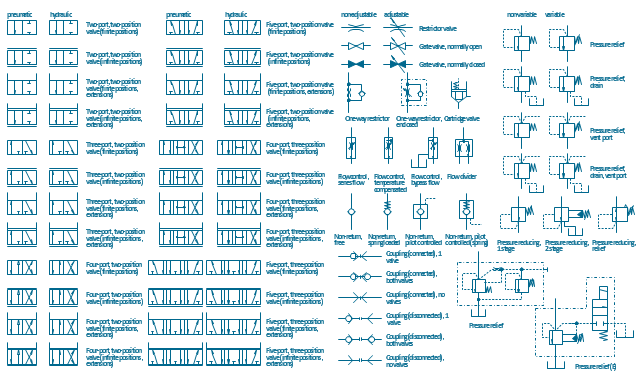
The vector stencils library "Fluid power valves" contains 93 symbols of pre-made hydraulic and pneumatic valves, including directional control valves, flow control valves, pressure control valves, and electrohydraulic and electropneumatic valves.
"Control valves are valves used to control conditions such as flow, pressure, temperature, and liquid level by fully or partially opening or closing in response to signals received from controllers that compare a "setpoint" to a "process variable" whose value is provided by sensors that monitor changes in such conditions.
The opening or closing of control valves is usually done automatically by electrical, hydraulic or pneumatic actuators. Positioners are used to control the opening or closing of the actuator based on electric, or pneumatic signals.
A control valve consists of three main parts in which each part exist in several types and designs: Valve's actuator, Valve's positioner, Valve's body.
" [Control valves. Wikipedia]
The shapes example "Design elements - Fluid power valves" was created using the ConceptDraw PRO diagramming and vector drawing software extended with the Mechanical Engineering solution from the Engineering area of ConceptDraw Solution Park.
"A piping and instrumentation diagram/ drawing (P&ID) is a diagram in the process industry which shows the piping of the process flow together with the installed equipment and instrumentation. ...
P&IDs play a significant role in the maintenance and modification of the process that it describes. It is critical to demonstrate the physical sequence of equipment and systems, as well as how these systems connect. During the design stage, the diagram also provides the basis for the development of system control schemes, allowing for further safety and operational investigations, such as a Hazard Analysis and Operability Study...
For processing facilities, it is a pictorial representation of:
Key piping and instrument details,
Control and shutdown schemes,
Safety and regulatory requirements,
Basic start up and operational information." [Piping and instrumentation diagram. Wikipedia]
The piping and instrumentation diagram template for the ConceptDraw PRO diagramming and vector drawing software is included in the Chemical and Process Engineering solution from the Engineering area of ConceptDraw Solution Park.
- Directional control valve
- Mechanical Drawing Symbols | Pneumatic 5-ported 3-position valve ...
- Flow Control Valve Symbol
- Valve Diagram
- Mechanical Drawing Symbols | Pneumatic 5-ported 3-position valve ...
- Pneumatic 5-ported 3-position valve template - Mac | Hydraulic 4 ...
- Hydraulic 5-ported 3-position valve template - Win | Directional ...
- Gate Valve Diagram
- Gate Valve Symbol
- Mechanical Drawing Symbols | Pneumatic 5-ported 3-position valve ...
- Pneumatic 5-ported 3-position valve template - Mac | Mechanical ...
- Mechanical Valve Symbols
- Mechanical Drawing Symbols | Directional control valve | Directional ...
- Mechanical Drawing Symbols | Pneumatic 5-ported 3-position valve ...
- Mechanical Drawing Symbols | Mechanical Drawing Software ...
- Hydraulic Valve Diagram Symbols
- Retract resistor check valve application | Fluid power valves - Vector ...
- Hydraulic 4-ported 3-position valve template - Win | Mechanical ...
- Valve Mechanical Diagram
- Mechanical Drawing Symbols | Pneumatic 5-ported 3-position valve ...

-piping-and-instrumentation-diagram-template.png--diagram-flowchart-example.png)