"Directional control valves route the fluid to the desired actuator. They usually consist of a spool inside a cast iron or steel housing. The spool slides to different positions in the housing, and intersecting grooves and channels route the fluid based on the spool's position. The spool has a central (neutral) position maintained with springs; in this position the supply fluid is blocked, or returned to tank. Sliding the spool to one side routes the hydraulic fluid to an actuator and provides a return path from the actuator to tank. When the spool is moved to the opposite direction the supply and return paths are switched. When the spool is allowed to return to neutral (center) position the actuator fluid paths are blocked, locking it in position. Directional control valves are usually designed to be stackable, with one valve for each hydraulic cylinder, and one fluid input supplying all the valves in the stack. Tolerances are very tight in order to handle the high pressure and avoid leaking, spools typically have a clearance with the housing of less than a thousandth of an inch (25 µm). The valve block will be mounted to the machine's frame with a three point pattern to avoid distorting the valve block and jamming the valve's sensitive components. The spool position may be actuated by mechanical levers, hydraulic pilot pressure, or solenoids which push the spool left or right. A seal allows part of the spool to protrude outside the housing, where it is accessible to the actuator. The main valve block is usually a stack of off the shelf directional control valves chosen by flow capacity and performance. Some valves are designed to be proportional (flow rate proportional to valve position), while others may be simply on-off. The control valve is one of the most expensive and sensitive parts of a hydraulic circuit." [Hydraulic machinery. Wikipedia]
The Windows template "Hydraulic 4-ported 3-position valve" for the ConceptDraw PRO diagramming and vector drawing software is included in the Mechanical Engineering solution from the Engineering area of ConceptDraw Solution Park.
www.conceptdraw.com/ solution-park/ engineering-mechanical
The Windows template "Hydraulic 4-ported 3-position valve" for the ConceptDraw PRO diagramming and vector drawing software is included in the Mechanical Engineering solution from the Engineering area of ConceptDraw Solution Park.
www.conceptdraw.com/ solution-park/ engineering-mechanical
Hydraulic directional control valve

"Hydraulics is a topic in applied science and engineering dealing with the mechanical properties of liquids. At a very basic level hydraulics is the liquid version of pneumatics. Fluid mechanics provides the theoretical foundation for hydraulics, which focuses on the engineering uses of fluid properties. In fluid power, hydraulics is used for the generation, control, and transmission of power by the use of pressurized liquids. Hydraulic topics range through some part of science and most of engineering modules, and cover concepts such as pipe flow, dam design, fluidics and fluid control circuitry, pumps, turbines, hydropower, computational fluid dynamics, flow measurement, river channel behavior and erosion." [Hydraulics. Wikipedia]
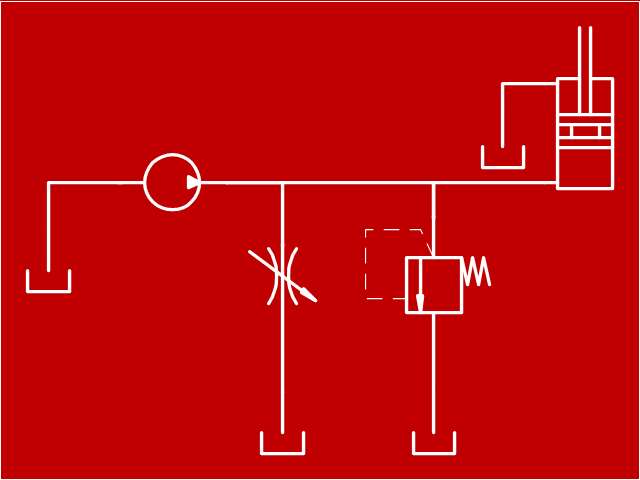
This hydraulic schematic example was redrawn using ConceptDraw PRO diagramming and vector drawing software from the Wikimedia Commons file: Skjematikk.GIF.
[commons.wikimedia.org/ wiki/ File:Skjematikk.GIF]
This file is licensed under the Creative Commons Attribution-Share Alike 3.0 Unported license.
[creativecommons.org/ licenses/ by-sa/ 3.0/ deed.en]
The engineering drawing example "Hydraulic schematic" was created using the ConceptDraw PRO diagramming and vector drawing software extended with the Mechanical Engineering solution from the Engineering area of ConceptDraw Solution Park.
Hydraulic schematic example
- Hydraulic Circuit Symbols
- Hydraulic schematic | Transmission paths - Vector stencils library ...
- Hydraulic 4-ported 3-position valve template - Win | Valves - Vector ...
- Design elements - Pumps | Pumps - Vector stencils library | Design ...
- Design elements - Hydraulic pumps and motors | Hydraulic circuits ...
- Mechanical Drawing Symbols | Hydraulic 4-ported 3-position valve ...
- Hydraulic Symbol Stencil
- Pneumatic 5-ported 3-position valve template - Mac | Mechanical ...
- Technical Engineering Drawing Symbols Hydraulic
- Hydraulic 4-ported 3-position valve template - Win | Design ...
- Pumps - Vector stencils library | Design elements - Hydraulic pumps ...
- Mechanical Drawing Symbols | Mechanical Engineering | Hydraulic ...
- Vector stencils library - IDEF3 object schematic symbols | Vector ...
- Fluid power equipment - Vector stencils library | Hydraulic 4-ported 3 ...
- Welding symbols | Hydraulic pumps and motors - Vector stencils ...
- Hydraulic 4-ported 3-position valve template - Win | Hydraulic 5 ...
- Cisco media - Vector stencils library
- Hydraulic Valve Symbols
- Hydraulic Circuit Design Online
- Mechanical Engineering | Mechanical Drawing Software ...