This is a schematic process flow diagram of the processes used in a typical oil refinery.
This process flow diagram (PFD) example was redesigned from the Wikimedia Commons file: RefineryFlow.png. [commons.wikimedia.org/ wiki/ File:RefineryFlow.png]
This file is licensed under the Creative Commons Attribution-Share Alike 3.0 Unported license. [creativecommons.org/ licenses/ by-sa/ 3.0/ deed.en]
"An oil refinery or petroleum refinery is an industrial process plant where crude oil is processed and refined into more useful products such as petroleum naphtha, gasoline, diesel fuel, asphalt base, heating oil, kerosene and liquefied petroleum gas. Oil refineries are typically large, sprawling industrial complexes with extensive piping running throughout, carrying streams of fluids between large chemical processing units. In many ways, oil refineries use much of the technology of, and can be thought of, as types of chemical plants. The crude oil feedstock has typically been processed by an oil production plant. There is usually an oil depot (tank farm) at or near an oil refinery for the storage of incoming crude oil feedstock as well as bulk liquid products.
An oil refinery is considered an essential part of the downstream side of the petroleum industry." [Oil refinery. Wikipedia]
The PFD example "Process flow diagram - Typical oil refinery" was created using the ConceptDraw PRO diagramming and vector drawing software extended with the Chemical and Process Engineering solution from the Chemical and Process Engineering area of ConceptDraw Solution Park.
Process Flow Diagram (PFD)
-process-flow-diagram---typical-oil-refinery.png--diagram-flowchart-example.png)
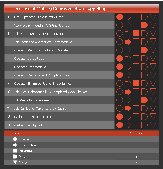
Flow process chart is used in quality control to display the action sequence of physical or manual process.
Flow process chart is useful for recording actions and documenting the production process.
Flow process chart helps to analyze and improve the process steps.
Flow process chart is more preferable than flowchart for documenting the mostly sequential processes.
Three types of flow process charts include: 1) man-type charts depicting the person actions, 2) material-type charts displaying the actions with product or material object, 3) equipment-type charts visualizing the useage of tools and equipment.
The set of symbols used in the flow process charts was developed by the American Society of Mechanical Engineers (ASME).
This flow process chart example was created using the ConceptDraw PRO diagramming and vector drawing software extended with the Matrices solution from the Marketing area of ConceptDraw Solution Park.
Flow process chart
- Crude oil distillation unit - PFD | Process flow diagram (PFD ...
- Process Flow Diagram Symbols | Process Flowchart | Process Flow ...
- Process flow diagram - Typical oil refinery | Natural gas condensate ...
- Process flow diagram - Typical oil refinery | Basic Flowchart Symbols ...
- Process flow diagram - Typical oil refinery | Crude oil distillation unit ...
- Process Flowchart | Flow chart Example . Warehouse Flowchart | Top ...
- Process Flowchart | Process flow diagram - Typical oil refinery | How ...
- Flow process chart | Land sales process flowchart | Sales Process ...
- Process Flowchart | Basic Flowchart Symbols and Meaning | Flow ...
- Sample Oil And Gas Process Flow Diagram In Pdf
- Basic Flowchart Symbols and Meaning | Flow chart Example ...
- Petroleum products yielded from one barrel of crude oil | Process ...
- Crude oil distillation unit - PFD | Process Flow Diagram Symbols ...
- Plant Layout Plans | Process flow diagram (PFD) template | Amine ...
- Flow process chart
- Business feedback loop | Sales Process Flowchart . Flowchart ...
- Crude oil distillation unit - PFD | Process flow diagram - Typical oil ...
- Process Flowchart | Basic Flowchart Symbols and Meaning | Flow ...
- Example Of Customer Feedback
- Process flow diagram