"A process flow diagram (PFD) is a diagram commonly used in chemical and process engineering to indicate the general flow of plant processes and equipment. The PFD displays the relationship between major equipment of a plant facility and does not show minor details such as piping details and designations. Another commonly used term for a PFD is a flowsheet. ...
Process flow diagrams of multiple process units within a large industrial plant will usually contain less detail and may be called block flow diagrams or schematic flow diagrams." [Process flow diagram. Wikipedia]
The process flow diagram (PFD) template for the ConceptDraw PRO diagramming and vector drawing software is included in the Chemical and Process Engineering solution from the Engineering area of ConceptDraw Solution Park.
Process flow diagram (PFD) template
-template-process-flow-diagram-(pfd)-template.png--diagram-flowchart-example.png)
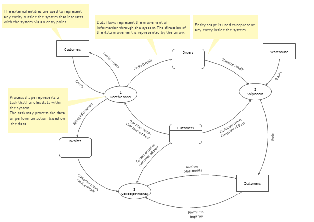
Data Flow Diagrams (DFD) visualize data flows in information systems.
They show: what kinds of data input to and output from the system; where the data come from and go to; where the data is stored.
DFDs are used for design and analysis of business and engineering information systems.
They are also used for data processing visualization.
They show: what kinds of data input to and output from the system; where the data come from and go to; where the data is stored.
DFDs are used for design and analysis of business and engineering information systems.
They are also used for data processing visualization.
DFD template
HelpDesk
How to Draw a Process Flow Diagram in ConceptDraw PRO

- Data flow Model Diagram
- Data Flow Diagrams (DFD)
- Flow Diagram Template Powerpoint
- Process Flowchart | Process flow diagram (PFD) template | Business ...
- Circular Flow Diagram Template
- Workflow Diagram Examples | Workflow Diagrams | Flow chart ...
- How to Draw a Chemical Process Flow Diagram | Chemical and ...
- Manufacturing 8 Ms fishbone diagram - Template | Data Flow ...
- Basic Flowchart Symbols and Meaning | Process Flowchart | Data ...
- Process Flowchart | Basic Audit Flowchart . Flowchart Examples ...
- Circular Diagram | Circular Arrow | Circular Flow Diagram Template ...
- Context Diagram Template | Data Flow Diagrams | Process ...
- Process Flowchart | Data Flow Diagrams | Basic Flowchart Symbols ...
- Gane Sarson Diagram | DFD, Gane-Sarson notation - Template ...
- Process Engineering | Process flow diagram (PFD) template ...
- Circular Flow Diagram Template | Basic Flowchart Symbols and ...
- Circular Flow Diagram Template | Circular Arrow | Circular arrows ...
- The Circular Flow Diagram | Circular Flow Diagram Template ...
- Process flow diagram (PFD) template | Flowchart Software | Cross ...
- Product Development Flow Chart Template