HelpDesk
How to Create a Bank ATM Use Case Diagram

 ATM UML Diagrams
The ATM UML Diagrams solution lets you create ATM solutions and UML examples. Use ConceptDraw PRO as a UML diagram creator to visualize a banking system.
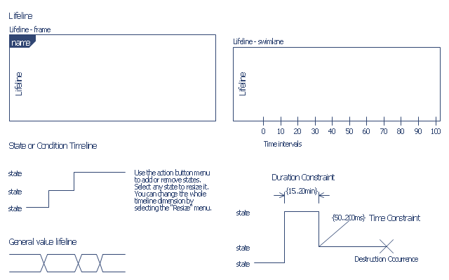
The vector stencils library "Bank UML timing diagram" contains 8 shapes for drawing UML timing diagrams.
Use it for object-oriented modeling of your bank information system.
"A timing diagram in the Unified Modeling Language 2.0 is a specific type of interaction diagram, where the focus is on timing constraints.
Timing diagrams are used to explore the behaviors of objects throughout a given period of time. A timing diagram is a special form of a sequence diagram. The differences between timing diagram and sequence diagram are the axes are reversed so that the time is increased from left to right and the lifelines are shown in separate compartments arranged vertically.
There are two basic flavors of timing diagram: the concise notation, and the robust notation." [Timing diagram. Wikipedia]
This example of UML timing diagram symbols for the ConceptDraw PRO diagramming and vector drawing software is included in the ATM UML Diagrams solution from the Software Development area of ConceptDraw Solution Park.
UML timing diagram symbols
- Timing Diagram For Atm Machine
- Timing Diagram Bank System Uml
- Diagramming Software for Design UML Timing Diagrams | UML ...
- UML Deployment Diagram Example - ATM System UML diagrams ...
- Diagramming Software for Design UML Timing Diagrams | Business ...
- Timing Diagram Example In Uml
- Diagramming Software for Design UML Timing Diagrams | UML ...
- Timing diagram | UML timing diagram - Template | Diagramming ...
- Design elements - Bank UML state machine diagram | How to ...
- Diagramming Software for Design UML Timing Diagrams | Timing ...
- UML Class Diagram Example for Transport System | Timing diagram ...
- Class Diagram Of Atm Machine In Ppt
- UML Diagram | How to Create a Bank ATM Use Case Diagram ...
- Diagramming Software for Design UML Timing Diagrams | Timing ...
- Diagramming Software for Design UML Timing Diagrams | Timing ...
- Timing diagram | Diagramming Software for Design UML Timing ...
- Timing diagram | UML Class Diagram Example for Transport System ...
- UML Deployment Diagram Example - ATM System | UML Use Case ...
- How To Draw Deployment Diagram