Wiring Diagram Symbols
A Wiring diagram is an electrical diagram, which shows the physical layout of electrical components and connections in an electrical system or circuit in a simple schematic view. The simplified wiring diagram symbols and lines are used to show the components. A Wiring diagram is an effective way to show all circuit devices and parts, included electrical equipment, electrical fixtures, sockets, switches, and many more, their location in a circuit, and how they are interconnected with electrical wires, how the wires are connected and where they are located in the electrical or electronic devices.
Wiring diagrams are used in a wide range of electrical and electronic fields, by electrical engineers, electrical inspectors, and electricians during the wiring and after its completion. They are necessary to build the electrical wiring in residential buildings and industries, to check and track their work, make repair works, and improvements, auto repair, and manufacture electronic devices. They help to plan the location of electrical outlets and light fixtures to avoid building code violations, mistakes, and future costly amendments. Wiring diagrams are also used by electrical equipment manufacturers and show the installation of wires in switchboards, panels, and other electrical equipment.
Wiring diagrams are a simple pictorial way to show electrical circuits and systems. They use universally accepted special graphical symbols for basic electronic and electrical components. The position of individual components within a circuit and their type are clearly identified by graphical symbols.
As for the connections, single conductors and multiple conductors bundled together and installed in the same channel are represented schematically by single lines in a diagram. Usually, bold lines are used to show the power circuits. Arrows are also used to indicate the direction of a current flow around a circuit or through the components.
Example 1. Wiring Diagram Symbols Library for Home Automation and Wiring Solution
Home Automation and Wiring solution for ConceptDraw DIAGRAM software offers the design elements — wiring diagram symbols, electric lighting objects, plugs, sockets, light switches, home appliances, and a lot of other pre-made vector design objects for simple creating professional-looking Wiring diagrams. Simply drop the required symbols from the libraries into your diagram, arrange, and connect them in the desired way. All symbols are vector and customizable by using the control handles. You can resize them without losing quality, rotate as necessary, change color, arrange several objects horizontally or vertically in one line, etc.
Use the Line tool to draw the connections or wires. Change the line's thickness and color depending on your requirements. In addition, the electrical symbols connected to the lines will remain connected even if you move the lines. Use smart connectors to provide the optimal route between objects and change it automatically when moving one of the connected objects. It's incredibly useful when you want to make some non-significant transformations on your diagram. You can also add the legend in your diagram and add descriptions for the symbols used in it.

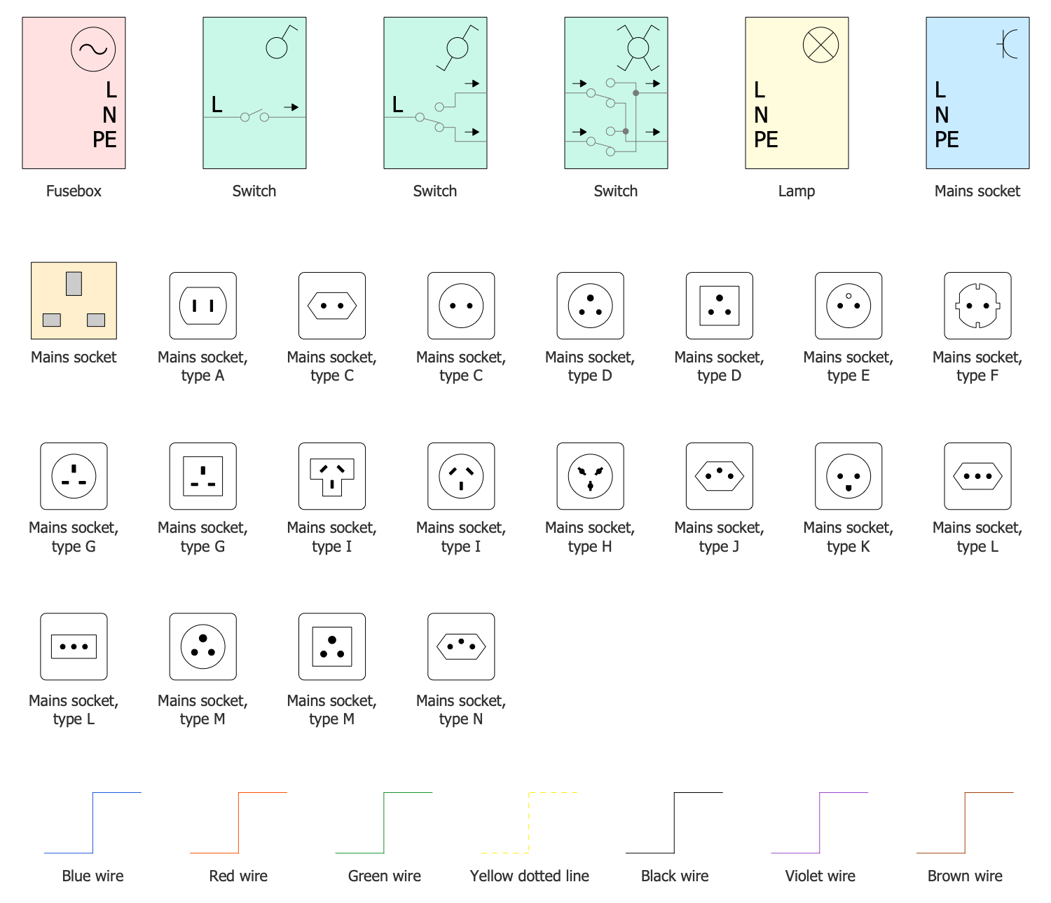
Example 2. Home Automation and Wiring Libraries Design Elements
Design effectively your Home Wiring Plans, Offices Wiring Diagrams, Electrical Wiring Blueprints, and other kinds of wiring diagrams from a blank sheet or use one of the predesigned samples included in the solution as a template and customize it. In addition, the included samples are good examples of wiring diagrams. You can also export the resulting diagram to different graphical formats and other applications, and share it with colleagues via email directly from the application.

Example 3. Wiring Diagram - Fusebox 2-Switches 2-Lamps Socket
The Wiring Diagram samples you see on this page were created in ConceptDraw DIAGRAM software using the drawing tools of the Home Automation and Wiring Solution. These examples successfully demonstrate the solution's capabilities and the professional results you can achieve using it. An experienced user spent 5-15 minutes creating each of these samples.
Use the drawing tools of the Home Automation and Wiring solution to design your own Home automation diagrams and infographics quick, easy, and effective.
All source documents are vector graphic documents. They are available for reviewing, modifying, or converting to a variety of formats (PDF file, MS PowerPoint, MS Visio, and many other graphic formats) from the ConceptDraw STORE. The Home Automation and Wiring Solution is available for ConceptDraw DIAGRAM users.