Made with
ConceptDraw
DIAGRAM 18

The Rack

The Rack Diagrams represent the frontal view of the rack with network equipment installed. They are helpful and widely used for choosing the equipment and racks to buy, and give the possibility to visually plan how to organize it on the racks.

Now creating of the Rack Diagrams is quite simple and quick thanks to the powerful drawing tools of the Rack Diagrams Solution from the Computer and Networks Area.

The Rack *

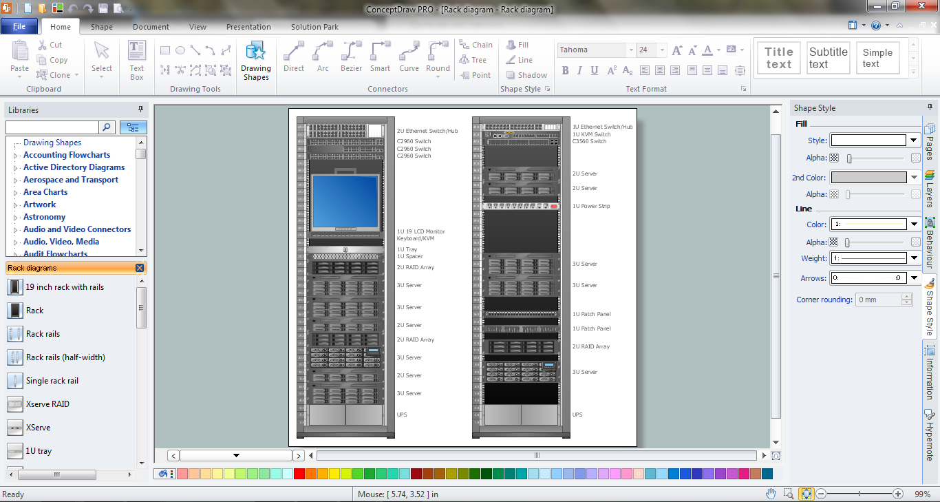
Example 1. The Rack Diagram in ConceptDraw DIAGRAM /p>

Rack Diagrams Solution provides the Rack Diagrams library with large collection of ready-to-use vector shapes. All that you need for designing the rack diagram is create the new document and simply drag on it the desired objects from the Rack Diagrams library.

Rack Diagrams Library Design Elements

Example 2. Rack Diagrams Library Design Elements

The predesigned shapes of the Rack Diagrams library are so different that you will exactly find the needed for you.

If you need to draw the rack diagram faster, you can use the ready templates or samples offered in ConceptDraw STORE and simply change them.

The Rack Diagram - Virtualized Computer Center

Example 3. The Rack Diagram - Virtualized Computer Center

The rack diagrams you see on this page were created in ConceptDraw DIAGRAM using the Rack Diagrams Solution. An experienced user spent 10-15 minutes creating every of these diagrams.

Use the Rack Diagrams Solution for ConceptDraw DIAGRAM software to create your own professional looking rack diagrams of any complexity fast and simply.

All source documents are vector graphic documents. They are available for reviewing, modifying, or converting to a variety of formats (PDF file, MS PowerPoint, MS Visio, and many other graphic formats) from the ConceptDraw STORE. The Rack Diagrams Solution is available for all ConceptDraw DIAGRAM or later users.


FIVE RELATED HOW TO's:
Entity Relationship Diagram (ERD) is the world-known way to show the logical structure of databases in visual manner. The best software tool for drawing Entity-Relationship Diagram is ConceptDraw DIAGRAM vector graphics software with Entity-Relationship Diagram (ERD) solution from Software Development area which gives the ability to describe a database using the Entity-Relationship model. The vector graphic diagrams produced using this solution can be successfully used in whitepapers, presentations, datasheets, posters, or any technical materials.Entity-Relationship Diagram *
Picture: Entity-Relationship Diagram
Related Solution:
Working as a designer, you might find developing projects exciting and difficult at the same time. It is a challenging task to create a usable interior design that will fulfill all the customer’s requirements. So, in order to aid yourself, you can use special software to create site plans, landscape designs, furniture layouts. This example of an interior plan introduces an internal area of a small cafe. The floor plan demonstrates interior angle "view from above". It involves many different elements of furniture such as tables , chairs and various cushioned furniture. Also it includes a kitchen fixtures and furniture. Making this plan was managed by the ConceptDraw Cafe and Restaurant Floor Plan solution. The libraries, composing this solution contain about vector graphic 300 objects. It can be use to help interior designers to develop interior design proposals, communicate ideas and concepts that relate to a interior design.Interior Design *
Picture: Interior Design
Related Solution:
It is important to have an electrical circuits scheme, when you plan a renovation or move to a new apartment. You have to arrange interior according to that plan, and it’s trouble-free to create wiring diagrams with ConceptDraw DIAGRAM , furthermore, this software has all the features needed to create an interior plan as well. So, get inspired by tons of examples included to ConceptDraw DIAGRAM solutions, and start your diagramming experience! A wiring diagrams, that are represented on this drawing was created to depict the components of the electrical circuit schemes. These diagrams are created to depict the information about circuit arrangements and connections. Wiring diagrams, in contrast to physical drawings, use standard symbol's notation to depict different circuit devices and connections. That is why, wiring diagrams are applied to discover and repair electrical and electronic circuits. The vector graphic objects provided by ConceptDraw Electrical Engineering solution can help any specialist in electric engineering to design electrical schemes, circuit and wiring plans, power systems charts, and Maintenance and Repair diagrams.Wiring Diagrams with ConceptDraw DIAGRAM
Picture: Wiring Diagrams with ConceptDraw DIAGRAM
Related Solution:
ConceptDraw DIAGRAM is perfect for software designers and software developers who need to draw Network Active Directory Diagrams.Network Diagramming Software <br>for Network Active Directory Diagrams *
Picture: Network Diagramming Software for Network Active Directory Diagrams
It is convenient to represent various routes, directions, roads on the directional maps and navigation schemes. ConceptDraw DIAGRAM diagramming and vector drawing software supplied with Directional Maps Solution from the Maps Area of ConceptDraw Solution Park is effective for drawing Directions Maps.Directions Maps *
Picture: Directions Maps
Related Solution:
ConceptDraw
DIAGRAM 18