Diode Symbol
A diode is an electronic device, which includes two electrodes and provides the flow of current in only one direction and blocks it in the reverse one. A diode has a low resistance in one direction and high resistance in the other.
Diodes are rated according to their type, voltage, current capacity, and have numerous applications. The key industries of using diodes are radio and television. Also, they are used in lighting, microwave and switching circuits. Due to unidirectional behavior, diodes help to convert alternating current (AC) to direct current (DC) as rectifiers, they also provide demodulation in radio receivers. Light-emitting diodes are used in electrical lighting and as status indicators on electronic devices. Diodes are also used as temperature sensors or voltage references. Being combined with other components, they can construct logic gates. The diodes control the flow of electrical current in a circuit and manage the ebbs and tides of current.
Early diodes were vacuum electron tubes or metal tubes used as rectifiers or detectors in electronic circuits. They have two electrodes: an anode and a heated cathode, charged positively and negatively correspondingly. The electrons flow only from the cathode to the anode in the diode, but not conversely. Being polarized components, diodes require a correct connection in a circuit and act as one-way switches for current.
Currently, the main types of diodes include p-n junction diodes, tunnel diodes, varactor diodes, zener diodes, photodiodes, PIN diodes, schotky diodes, light emitting diodes, laser diodes, and avalanche diodes.
Semiconductor diodes are the most common type. The current can flow through a diode forward-biased or reverse-biased. Diodes are "forward biased" when conduct electricity in the forward direction and “reverse biased” when are connected within a circuit in the reverse direction, act as insulators, and do not permit current to flow.
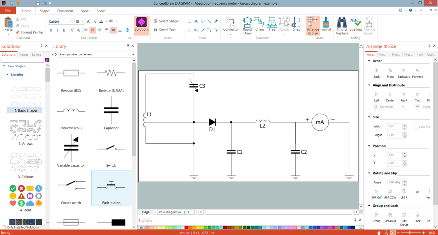
Example 1. Diode Symbol in Circuit Diagrams Design
Semiconductor diodes with p-n junction are the most used, they are connected to two electrical terminals and applied as rectifiers. Most diodes are made of silicon or germanium, but other semiconducting materials are also used. A working principle of the diodes depends on the interaction of n-type and p-type semiconductors. The dominant majorities are charge carriers. A p-type semiconductor has a high number of holes and a few free electrons, while an n-type semiconductor vice versa has a lot of free electrons and a low number of holes. In this type of diode, the electrons in n material are charge carriers and fill holes in p material. The depletion region is formed between these two materials. When n-type and p-type materials come in contact, the carriers that are in majority diffuse to another side through the depletion region and recombine there with minority carriers. Being "forward biased", a p-n junction behaves as a short circuit and as an open circuit when it is "reverse biased".
Zener diodes, varactor diodes, and light-emitting diodes (LEDs) are examples of p-n junction diodes. Light-emitting diodes emit light when a current flows through them. Zener diodes are used to regulate voltage and support constant voltage. Varactor diodes are used in electronically tuned radio and TV receivers. The change of voltage in varactor diodes causes the variation in their capacitance. Sometimes, several p-n junction diodes are connected in series and make a rectifier. Avalanche diodes protect circuits from high-voltage surges. Tunnel diodes, Gunn diodes, IMPATT diodes generate radio-frequency oscillations, exhibit negative resistance, and are used in microwave and switching circuits.

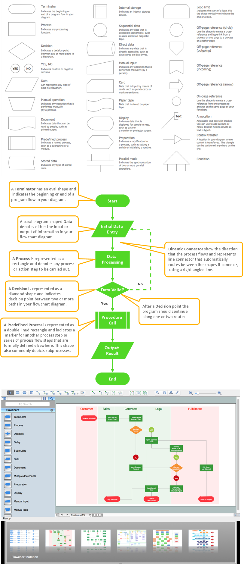
Example 2. Basic Active Components Library Design Elements
A diode symbol is represented by a triangle (arrow) with a line near it across one vertex. The direction of the current flow is opposite to the direction of the arrow on a diode symbol.
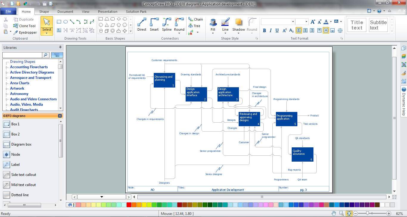
ConceptDraw DIAGRAM software supplied with Basic Circuit Diagrams solution includes 5 libraries with a collection of predesigned vector pictograms and symbols including diode symbol to create Circuit Diagrams without effort. Using them the Electric circuit diagrams, Electronic circuit diagrams, Lighting schematics, Basic 3-phase configurations, and many more kinds of Circuit Diagrams are designed equally easy by both professionals and beginners.

Example 3. Circuit Diagram - Halfwave Rectifier
The Circuit Diagrams samples you see on this page were created in ConceptDraw DIAGRAM software using the drawing tools of the Basic Circuit Diagrams Solution. These examples successfully demonstrate the solution's capabilities and the professional results you can achieve using it. An experienced user spent 5-15 minutes creating each of these samples.
Use the drawing tools of the Basic Circuit Diagrams solution to design your own Circuit Diagrams and schematics quick, easy, and effective.
All source documents are vector graphic documents. They are available for reviewing, modifying, or converting to a variety of formats (PDF file, MS PowerPoint, MS Visio, and many other graphic formats) from the ConceptDraw STORE. The Basic Circuit Diagrams Solution is available for ConceptDraw DIAGRAM users.


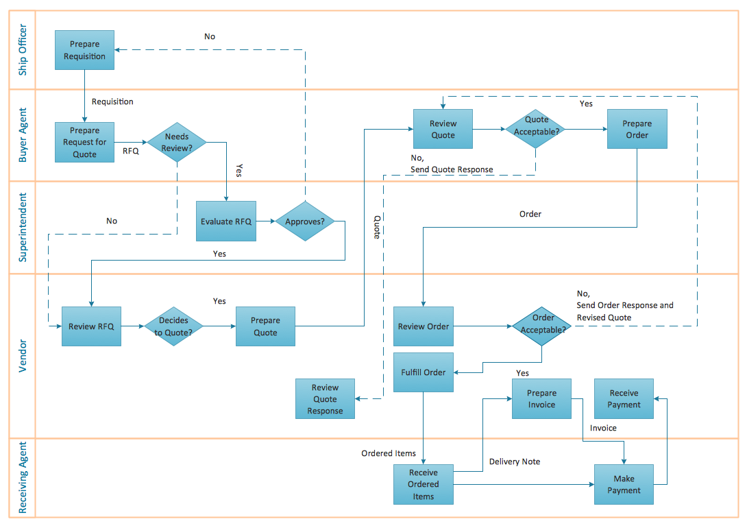
It is effective to use professional software for the sales process management. ConceptDraw DIAGRAM diagramming and vector drawing software extended with Sales Flowcharts solution from the Marketing area of ConceptDraw Solution Park is the best choice.