Logic Diagram
Logic diagrams are the main type of diagrams used to depict logical circuits, show how the components and logic gates are connected in a digital circuit. They have an extended range of applications including electrical, electronic, and digital engineering, and solid-state industry. Logic diagrams depict the operation circuits and systems, start and stop components, and logical relationships of project activities. They are used at industrial facilities, help to design solid-state components like computer chips and make a graphical representation of a program using formal logic. These are also the schematics of working the pumps, and other equipment.
Logic diagrams allow predicting the expected output according to the included gates. They give information about operating systems and their components, input signals, and help to solve logical problems. Logic diagrams support understanding how the systems or components operate and how they respond to various combinations of inputs.
Logic diagrams help receive precise results and avoid financial losses, time wastage, and getting unexpected results. Due to Logical diagrams, any detected inconsistencies in the circuit are easily corrected yet at the stage of design, not when it is implemented.
The logic symbols used in a Logic diagram are called logic gates. They are the main components of digital electronics and the basic building blocks of digital circuits. Each logic gate performs one or several Boolean logic operations AND, OR, XOR, NAND, NOR, NOT, XNOR. At this, AND, OR, and NOT are the basic types of logic gates and other gates are their combinations. NOT gate is used in conjunction with AND and OR gates and forms NAND and NOR gates correspondingly. XOR is an exclusive OR and XNOR is an exclusive NOR.
Each logic gate has only two states on / off, 1 / 0, or True / False. NOT gate takes only one input digit, all other types of logic gates take two binary input digits and produce one binary output digit. The state of the output is determined by the state of the inputs to the gate. At this, each type of gate responds differently to various combinations of inputs. The logic gates and their combinations are depicted by special symbols on the Logic diagram.
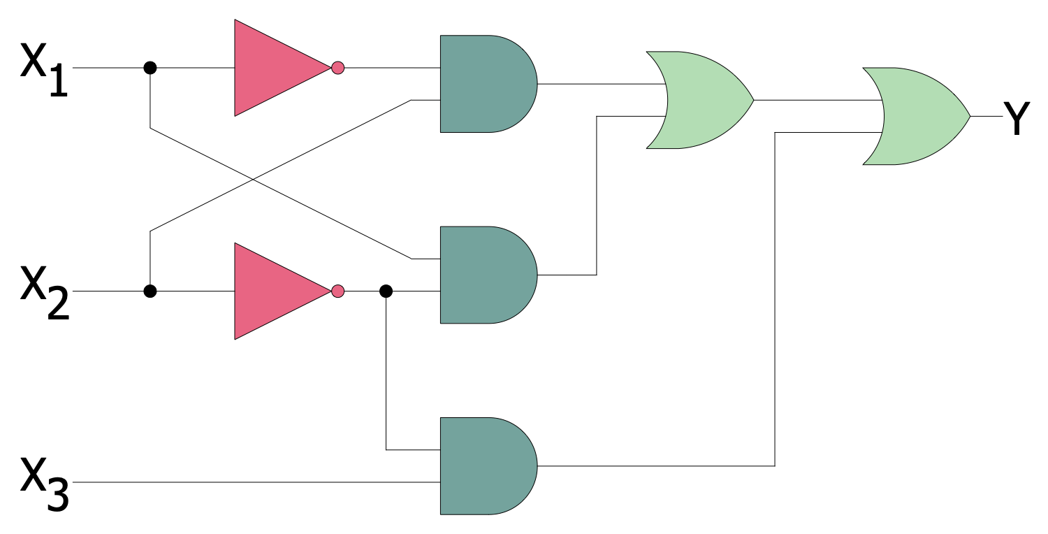
Example 1. Combinatorial Logic Diagram
Being sent to the input points, the signals pass through the logic gates and according to the gate's type the output is produced. Logic diagrams are often supplied with Truth tables that depict the final outputs produced by the devices when the input signals are entered. Truth tables help to assess the output that is 0 or 1, and correct circuits for better results. The number of inputs that a gate can have is not limited.

Example 2. Digital Electronics Libraries
The professional design software ConceptDraw DIAGRAM enhanced with Digital Electronics solution includes a collection of pre-made globally recognizable vector elements to create efficiently and faster Logic diagrams, Logic circuits, Digital electronic circuits, Computer logic diagrams, Process control logic diagrams, etc. It is useful for engineers, electronic designers, facility operators, and technical staff.

Example 3. Flip-Flop Logic Circuit
Digital Electronics solution also offers a set of pre-made samples including the examples of logic circuits, flip flop logic circuit. You can use the included samples as templates to create your own diagrams fast and easily. You can also easily save and export your Logical diagrams to other applications directly from the program.

Example 4. Digital Logic Circuit
The Logic Diagram samples you see on this page were created in ConceptDraw DIAGRAM software using the drawing tools of the Digital Electronics Solution. These examples successfully demonstrate solution's capabilities and the professional results you can achieve using it. An experienced user spent 5-10 minutes creating each of these samples.
Use the drawing tools of the Digital Electronics solution to design your own Digital Electronics Infographics quick, easy, and effective.
All source documents are vector graphic documents. They are available for reviewing, modifying, or converting to a variety of formats (PDF file, MS PowerPoint, MS Visio, and many other graphic formats) from the ConceptDraw STORE. The Digital Electronics Solution is available for ConceptDraw DIAGRAM users.