Electrical Substation Diagram
Electrical substation is a part of an electric utility’s system connecting its elements like generators, distribution lines, transmission lines, utility systems. It is involved in the generation, transmission, and distribution of electric energy. The main components of electrical substation include power transformer, bus-bar, insulator, lightning arrester, circuit breaker. The main assignment is transforming energy voltage from high to low and reverse.
A transmission substation connects at least two transmission lines. They may have the same voltage or different. Typically, on the way from a generating station to end consumers, electric power flows through several substations with different voltage levels. In this way, the voltage is changed from high to the household utilization voltage by means of transformers use.
There are many types of electric substations: transmission, sub-transmission, distribution, collector, converter substations. Transmission substations can range from simple to complex and deal with high voltage. Distribution substations serve to transfer power from the transmission system to the distribution system, they reduce voltage to a level suitable for local distribution. Collector substations are used in distributed generation projects and resemble distribution substations. The difference consists in power flowing in the opposite direction, from the wind turbines or inverters up into the transmission grid. The transformers at the collector substations frequently need to increase the voltage to transmission level. Converter substations contain power electronic devices, they are used to change the frequency of current and to convert current from alternating to direct or reverse.
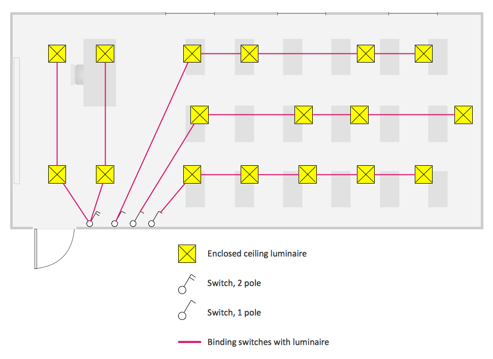
Electrical Substation Diagram is used to show the schematic of the arrangement of electrical equipment in the electrical substation and principles of its work. It illustrates the arrangement of feeders, transformers, isolators, circuit breakers, and else equipment, and their connections within an electrical substation.
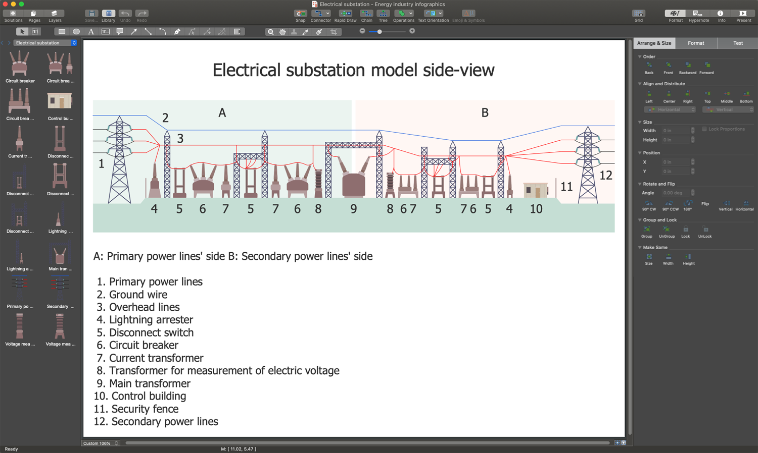
Example 1. Electrical Substation Diagram in ConceptDraw DIAGRAM
ConceptDraw DIAGRAM software and ConceptDraw Solution Park offer the Energy Industry Infographics solution with powerful drawing tools and collection of special energy signs and pictograms. Use them to greatly simplify your work in design of the energy industry infographics, illustrations, diagrams including electrical substation diagram, distribution system diagram, energy intelligence dashboards, electricity grid schematics, and many more.

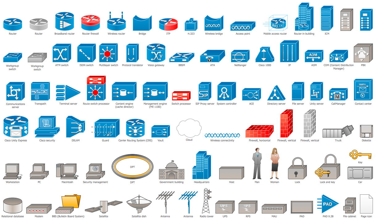
Example 2. Electrical Substation Library Design Elements
The Electrical Substation Diagram you see on this page was made using the vector stencil libraries from the Energy Industry Infographics Solution for ConceptDraw Solution Park. An experienced user spent 10 minutes creating this sample.
Use the Energy Industry Infographics Solution for ConceptDraw DIAGRAM software to develop your own professional-looking diagrams related to the energy industry quickly, simply, and effectively.
The possibility of exporting to a variety of popular graphical formats (PNG, JPEG, JPG, GIF, TIF, TIFF, BMP, DIB, EMF, SVG) and file formats like Microsoft PowerPoint (PPT), Adobe Acrobat (PDF), Microsoft Visio (VDX, VSDX), Adobe Flash (SWF), Encapsulated PostScript (EPS), HTML, opens wide opportunities for you.