Decoder
A decoder is an electronic circuit that retrieves original data, signals, messages, or other information coded by an encoder. Thus, it performs the operations reverse to ones of an encoder, it decodes the information. A decoder includes multiple inputs and multiple outputs and converts a unique combination of input states to a specific combination of output states.
There are different types of decoders depending on the areas in which they are used, and the number of inputs and outputs. Binary or line decoders convert binary information from the n coded inputs to a maximum of 2n outputs (n-to-2n decoder). For example, these are 1-to-2, 2-to-4, and 4-to-16 binary decoders. Increasing the number of inputs leads to increasing the number of outputs. Sometimes, several small decoders are combined together. Widely used decoders are often produced in the form of standardized ICs. Usually, the binary decoders are implemented as a stand-alone integrated circuit or as a part of a complex IC.
Audio decoders convert digital audio data streams to analog. Video decoders are electronic circuits that convert analog video signals to digital video. They are used in video capture devices and frame grabbers. Often, video decoders consist of a single integrated circuit chip and allow controlling specific video characteristics like contrast, hue, and saturation.
Compression decoders convert compressed data (audio, video, or images) to an uncompressed form. Instruction decoders convert computer instructions into CPU control signals. Quadrature decoders convert signals from incremental encoders into counter-control signals. Cascading decoders are binary decoders cascaded together and forming a large decoder circuit.
In addition to integer data inputs, some decoders also have one or more enable inputs. The enable input takes one of two states on or off and according to it the decoder's outputs are forced to active or inactive states. Decoding is used in various applications including data multiplexing, instruction decoding, 7 segment display and memory address decoding, port-mapped I/O, and television signals from a satellite. AND gate is also the decoder circuit.
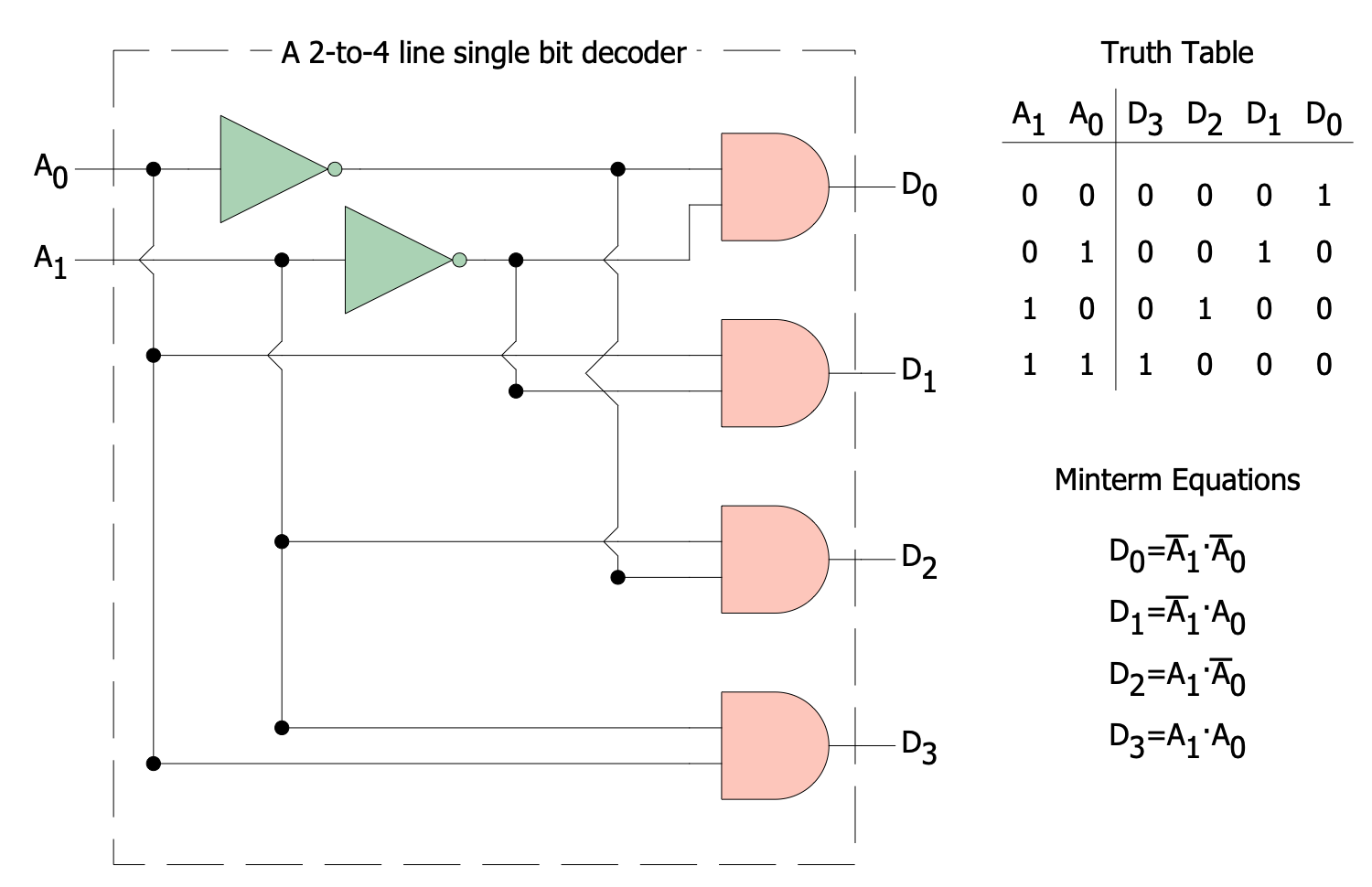
Example 1. 2-to-4 Line Single-Bit Decoder
ConceptDraw DIAGRAM software enhanced with Digital Electronics solution includes an enormous collection of predesigned digital electrical symbols, design elements — electronic logic, connections, logic gate symbols of different kinds, which suit the best for creating professional Electrical and Electronic diagrams, Electrical circuits, schematics of coders and decoders of various types.

Example 2. Digital Electronics Libraries
All included symbols, elements and pictograms are vector and gathered in 9 thematic libraries:
- Electronic Logic
- Flip Flop Symbols
- Integrated Circuits
- Logic Gates ANSI
- Logic Gates BS
- Logic Gates DIN
- Logic Gates IEC
- Logic Gates NEMA
- Displays and Programming Connections

Example 3. Single-Bit 1-to-4 Line Demultiplexer
The samples you see on this page were created in ConceptDraw DIAGRAM software using the drawing tools of the Digital Electronics Solution. These examples successfully demonstrate solution's capabilities and the professional results you can achieve using it. An experienced user spent 10-15 minutes creating each of these samples.
Use the drawing tools of the Digital Electronics solution to design your own Digital Electronics Infographics quick, easy, and effective.
All source documents are vector graphic documents. They are available for reviewing, modifying, or converting to a variety of formats (PDF file, MS PowerPoint, MS Visio, and many other graphic formats) from the ConceptDraw STORE. The Digital Electronics Solution is available for ConceptDraw DIAGRAM users.

.png)
