Antennas
What is an antenna?
The antenna is the most important part of wireless communication systems. It is a metallic device used to receive, capture and transmit radio, electromagnetic, and microwave signals. The antenna operates as a conductor and resonant device in the narrow frequency band.
The different kinds of antennas are applied in radio, television, broadcasting, satellite, and cellular systems and ensure fast and efficient communications. They are responsible for the transmission and collection of electromagnetic radiation. The transmitting antenna receives an RF signal or an electrical signal from the transmission line and then converts it into radio signals, a radio wave, or electromagnetic energy to be transmitted into space. The receiving antenna performs the same process in reverse order, it captures electromagnetic waves or radio signals from space, converts them into electrical power of electronic signals, and transmits them to the transmission line.
The antennas are the basic components of any electrical circuit, they provide interconnection between a transmitter and free space, and free space and receiver. Being invented in 1888 in Germany, they are currently available in various kinds with different characteristics according to the application and function they realize. The antennas are differentiated in shape, size, material, signal bandwidth, transmission range, gain, polarization, impedance, radiation pattern, beamwidth, and in more characteristics.
The properties of antennas include:
- gain — the intensity of the waves, which the antenna transmits;
- directivity — the concentration of radiation in the direction of maximum radiation;
- bandwidth — the range of frequencies on which the antenna can operate correctly;
- effective length — the length of the free space in a conductor;
- polarization — the direction of the electromagnetic fields produced by the antenna when it radiates energy, and more others.
Which Software is Best for Antenna Design?
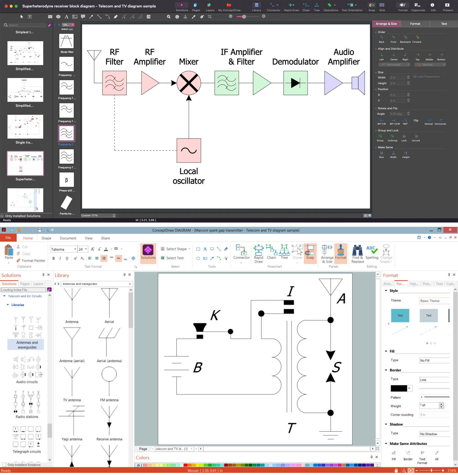
Use the drawing tools of the Telecom and AV Circuits solution to design your own Telecom and AV Circuits diagrams and infographics quick, easy, and effective.

Example 1. Creating Circuits with Antennas in ConceptDraw DIAGRAM
What are the Different Classification of Antennas?
Small antennas are used in television while large antennas capture signals from the satellite. One differs also two main categories: internal and external antennas. The internal antennas are out of reach to the end user. They are small chip or PCB-etched antennas integrated onto the board or flexible printed circuit embedded in an enclosure of mobile and other electronic devices. The external antennas are mounted on the outside of the device’s enclosure via an RF connector. The massive external antennas are installed in cellular and satellite base stations.
Moreover, there are omni-directional, directional, and semi-directional antennas. Each type has unique characteristics and applications. Omni-directional antennas radiate energy equally in all directions in a plane. The propagation of semi-directional antennas is limited by a specific angle. Directional antennas are effective in one direction, they have a narrow beam, provide a highly directional propagation and have a longer coverage distance than other types of antennas.
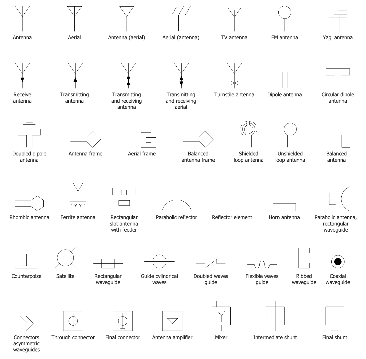
Example 2. Antennas and Waveguides Design Elements
Some kinds of antennas are:
- Aerial antenna
- FM antenna
- Receive antenna
- Transmitting antenna
- Dipole antenna
- Turnstile antenna
- Yagi antenna
- Turnstile antenna
- Schielded loop antenna
- Ferrite antenna
Telecom and AV Circuits solution for ConceptDraw DIAGRAM includes the predesigned vector symbols for all these antennas and many more others. They are included in the Antennas and Waveguides library. Other libraries of this solution offer design elements — audio circuits, video and TV symbols, radio stations and telegraph symbols, and more. The solution also contains large variety of predesigned thematic samples, which are useful as examples and templates for your own charts.
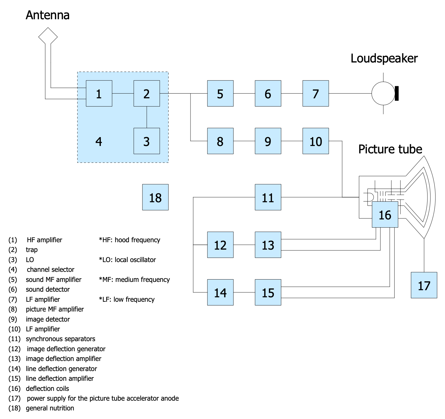
Example 3. Black and White TV Receiver Block Diagram
The Telecom and AV Circuits samples you see on this page were created in ConceptDraw DIAGRAM software using the drawing tools of the Telecom and AV Circuits Solution. These examples successfully demonstrate the solution's capabilities and the professional results you can achieve using it. An experienced user spent 5-15 minutes creating each of these samples.
All source documents are vector graphic documents. They are available for reviewing, modifying, or converting to a variety of formats (PDF file, MS PowerPoint, MS Visio, and many other graphic formats) from the ConceptDraw STORE. The Telecom and AV Circuits Solution is available for ConceptDraw DIAGRAM users.

