Made with
ConceptDraw
DIAGRAM 18

Analog Circuits

Modern society widely uses information, electrical and electronic technologies and devices to gather, store, process, and pass various information. The introduction of technical and technological innovations and the development of a substantial amount of modern electronics cause high progress in various fields. Currently, advanced knowledge and methods are used to explore and solve complex engineering tasks including electronic engineering tasks.

We live in an analog world and all real-world signals are analog. They are continuously variable signals in the form of continuous waves and include light, sound, pressure, temperature, motion, tones, etc. Analog waves are smooth and incredibly sensitive to the noise in the environment because noise can distort the signal waveform and cause a loss of information. At the same time, working with continuous analog circuits can decrease noise. Modern electrical engineering offers a lot of electronic and digital devices, but before they can perform any operations with real-world analog signals, these signals should be converted to digital ones.

Analog circuits are a type of electronic circuits that process analog signals and data. They give electronic representations of the physical world. The development of analog circuits including analog integrated circuits preceded digital circuits. The analog input signal is directly fed to the analog circuit without any conversions and any loss and then is processed. The amplification and decrease of a signal are possible.
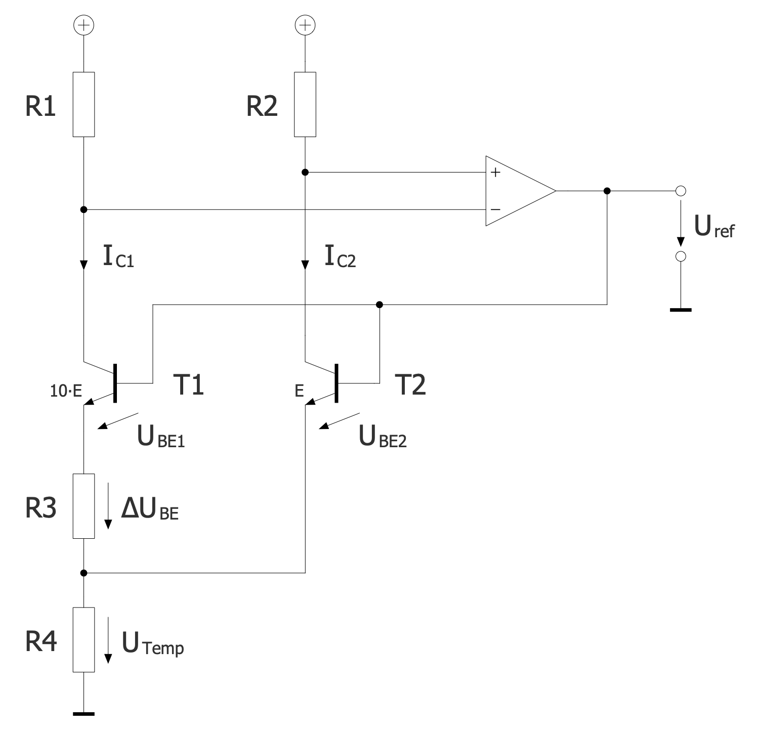
Analog Circuits - Band Gap Reference Circuit

Example 1. Analog Circuits - Band Gap Reference Circuit

Analog circuits are extensively used in various fields of electrical and electronics engineering and are part of many communications devices. They consist of a combination of active and passive components: resistors, transistors, diodes, capacitors, op-amps, and so on. Active components like diodes and transistors in combination with passive components like resistors and capacitors process signals. High-speed transistors are often an essential part of analog circuits.

Analog schematics show key components of analog circuits, communications systems, and other systems. They reflect a proportional representation of the real-world signals in electronic voltage or current. There are two types of analog circuits based on the used components and circuit behavior. These are active circuits like amplifiers and passive circuits like pass filters. The interconnection of several analog circuits, where each circuit performs a specific task, allows the creation of a complex electronic device or system. The manufacturing of analog circuits is often realized by soldering discrete components on a breadboard.
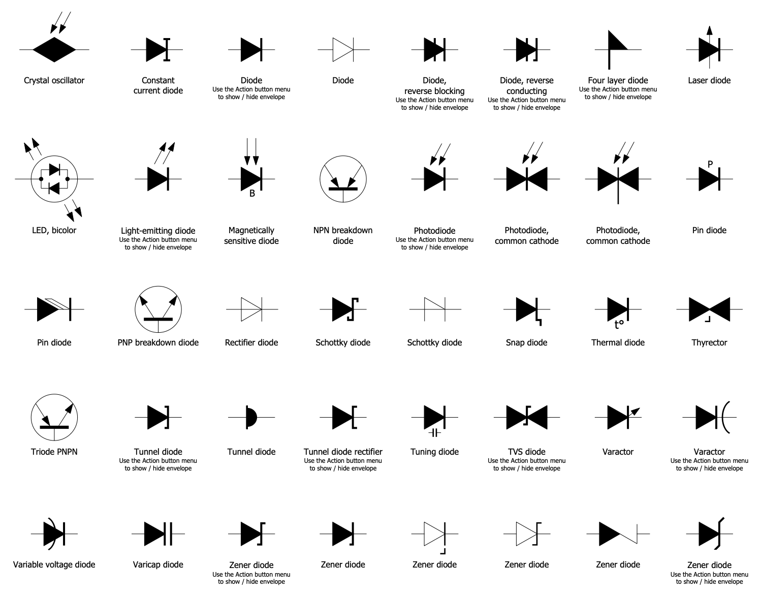
Semiconductor Diodes Library Design Elements

Example 2. Semiconductor Diodes Library Design Elements

Analog Electronics solution includes samples of some basic analog circuit configurations and a set of libraries with predesigned vector elements useful to create analog circuits in a few minutes:

  • Sensors and Transducers
  • Semiconductor Diodes
  • Electrical Signal Connectors
  • Transistors
  • Field Effect Transistors
  • Piezoelectric Crystals
  • Thyristors Diacs Triacs

Use this solution to design efficiently analog circuits, show how they function and how differ from digital circuits. It is useful in all stages of electronic engineering: development of electronic circuits, documentation, production, marketing, and selling of electronic products. A variety of schematics that you can design using ConceptDraw DIAGRAM and Analog Electronics solution is enormous. A large collection of ready-made examples of analog electrical engineering circuits is also included. These include two transistor feedback amplifier, unipolar stepper motor driver, band gap reference circuit, and many more.
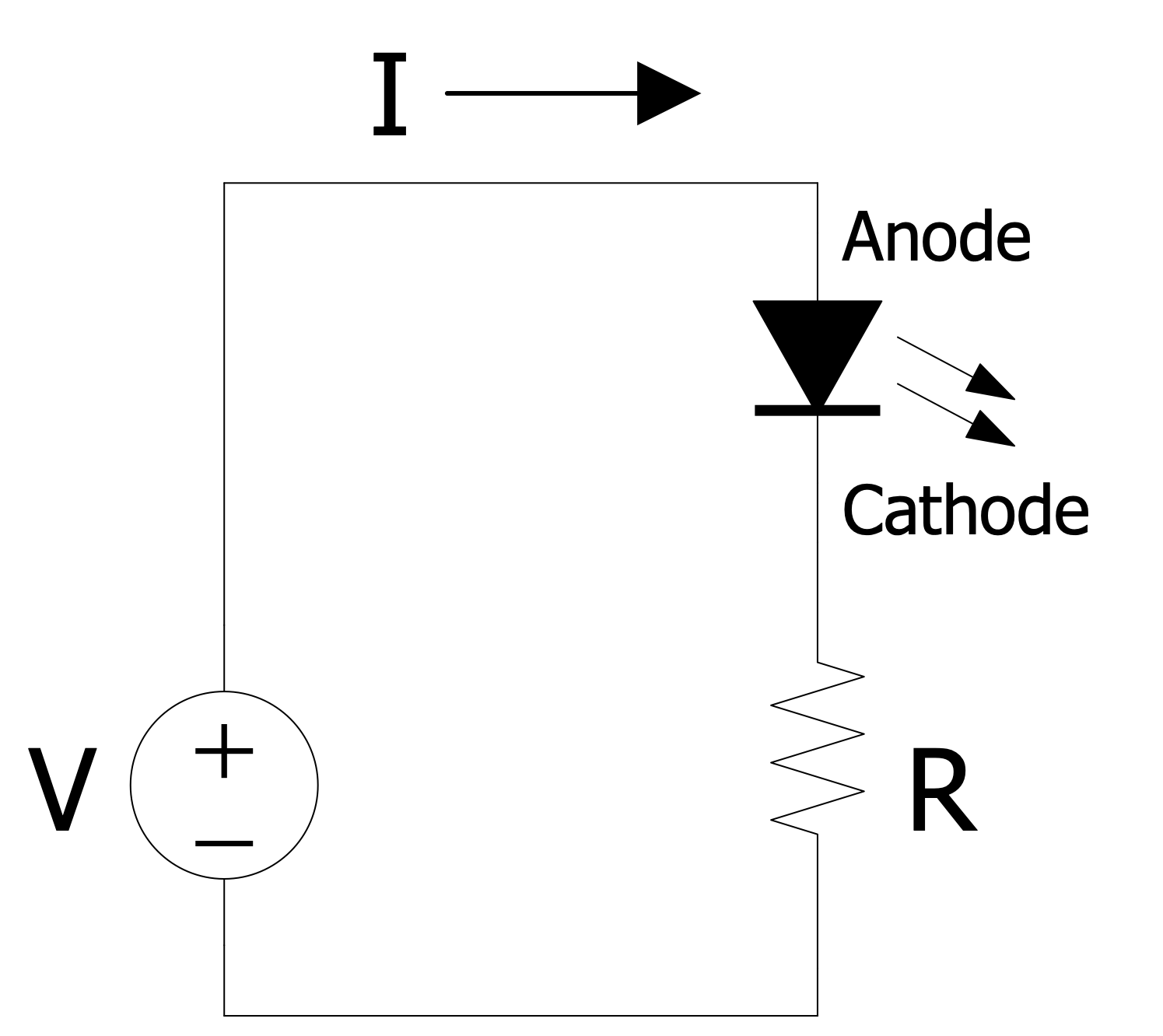
Analog Circuits - LED Circuit

Example 3. Analog Circuits - LED Circuit

The Analog Electronics samples you see on this page were created in ConceptDraw DIAGRAM software using the drawing tools of the Analog Electronics Solution. These examples successfully demonstrate the solution's capabilities and professional results you can achieve using it. An experienced user spent 5-10 minutes creating each of these samples.

Use the drawing tools of the Analog Electronics solution to design your own Analog Electronics Infographics quick, easy, and effective.

All source documents are vector graphic documents. They are available for reviewing, modifying, or converting to a variety of formats (PDF file, MS PowerPoint, MS Visio, and many other graphic formats) from the ConceptDraw STORE. The Analog Electronics Solution is available for ConceptDraw DIAGRAM users.



NINE RELATED HOW TO's:
Program Structure Diagram is a visual representation of a program's organization, showing its components and their relationships.Program Structure Diagram
Picture: Program Structure Diagram
Desbloquee el lenguaje de los diagramas de flujo con nuestra guía de símbolos de diagramas de flujo. 🔸 Todo lo que necesita saber sobre los conceptos básicos del diagrama de flujo, desde ✔️ puntos de decisión hasta ✔️ pasos del proceso, explore el significado detrás de cada símbolo y domine el arte de crear representaciones visuales claras y efectivas de sus procesos.Symboles Organigramme
Picture: Symboles Organigramme
Related Solution:
The Accounting flowchart shows how information flows from source documents through the accounting records. The are based on the accounting procedures or processes. Flowcharts are used to represent accounting information in a system. There are special symbols which are used to create accounting flowcharts. Try conceptdraw flowcharting set of symbols to draw a professional charts.Why Flowchart Important to<br> Accounting Information System? *
Picture: Why Flowchart Important to Accounting Information System?
Related Solution:
In ConceptDraw DIAGRAM it really is sp simple to draw even the most complex cross-functional flowcharts. Use the RapidDraw technology and Cross-Functional libraries in ConceptDraw DIAGRAM for the best results.How to Simplify Flow Charting — Cross-functional Flowchart
Picture: How to Simplify Flow Charting — Cross-functional Flowchart
Related Solution:
ConceptDraw DIAGRAM is a software for simplу depicting the business processes based on BPMN 2.0. Business Process Diagrams Cross-Functional-Flowcharts, Workflows, Process Charts, IDEF0 and IDEF2, Timeline, Calendars, Gantt Charts, Business Process Modeling, Audit and Opportunity Flowcharts and Mind Maps (presentations, meeting agendas).Business Process Modeling Notation *
Picture: Business Process Modeling Notation
Related Solution:
Electronic components have two or more electrical terminals (or leads) aside from antennas which may only have one terminal. These leads connect to create an electronic circuit with a particular function (for example an amplifier, radio receiver, or oscillator). Basic electronic components may be packaged discretely, as arrays or networks of like components, or integrated inside of packages such as semiconductor integrated circuits, hybrid integrated circuits, or thick film devices. 26 libraries of the Electrical Engineering Solution of ConceptDraw DIAGRAM make your electrical diagramming simple, efficient, and effective. You can simply and quickly drop the ready-to-use objects from libraries into your document to create the electrical diagram.Electrical Symbols — Composite Assemblies *
Picture: Electrical Symbols — Composite Assemblies
Related Solution:
There are many tools to manage a process or to illustrate an algorithm or a workflow. Flowcharting is one of those tools. However, it may be difficult to show complex processes that require multiple attributes or several people in a simple flowchart, so a cross-functional flowchart would be a solution for that situation. To create such flowchart, group processes and steps to labeled rows or columns, and divide those groups with horizontal or vertical parallel lines. It is worth mentioning that there are different types of cross-functional flowcharts, like opportunity or deployment flowchart. This diagram shows a cross-functional flowchart that was made for a trading process. It contains 14 processes, distributed through 5 lines depicting the participants who interact with the process. Also there are connectors that show the data flow of information between processes. The cross-functional flowchart displays a detailed model of the trading process, as well as all participants in the process and how they interact with each other. The lines in the flowchart indicates the position, department and role of the trading process participants.Cross-Functional Flowchart
Picture: Cross-Functional Flowchart
Related Solution:
When talking about engineering, one should define all the terms used, so anybody could understand the topic. Typical network glossary contains definitions of numerous network appliances, types of networks and cable systems. The understanding of basic is crucial for server management, network administration and investigating problems. The network glossary defines terms related to networking and communications. The most of glossary items has their visual representation in ConceptDraw DIAGRAM libraries of the Computer Network Diagrams solution. This illustration presents a local area network (LAN) diagram. It designed to show the way the interaction of network devices in a local network. The diagram uses a library containing symbols of network equipment, connections and the end-point devices such as network printer, hubs, server, modem and finally computers (PC, mac, laptop). This diagram depicts a physical LAN topology.Network Glossary Definition *
Picture: Network Glossary Definition
Related Solution:
It’s very important for any establishment to have a fire exit plan and to train it several times a year. The plan must be put on each floor of the building in a way that it could be easily seen. To make the plan clear and descriptive, you should look through examples and then create one for you your building. Find out the fire exit plan example created with ConceptDraw DIAGRAM and its Fire and Emergency Plans solution. This plan is a floor plan that shows the ways in which people inside the building can be evacuated in the event of a fire. The location of telephones, fire extinguishers and first aid kits are indicated on the fire exit plan. The Legend in the lower right corner of the plan makes it clear and easy-to-read. Such plan should be placed on the wall on each floor of the building.Fire Exit Map Example
Picture: Fire Exit Plan. Building Plan Examples
Related Solution:
ConceptDraw
DIAGRAM 18