The vector stencils library "DFD, Yourdon and Coad notation" contains 22 DFD elements.
Use it for drawing data flow diagrams (DFD) using Yourdon/ DeMarco notation in the ConceptDraw PRO diagramming and vector drawing software extended with the Data Flow Diagrams solution from the Software Development area of ConceptDraw Solution Park.
Use it for drawing data flow diagrams (DFD) using Yourdon/ DeMarco notation in the ConceptDraw PRO diagramming and vector drawing software extended with the Data Flow Diagrams solution from the Software Development area of ConceptDraw Solution Park.
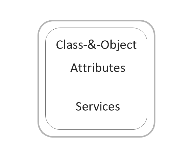
Class and object
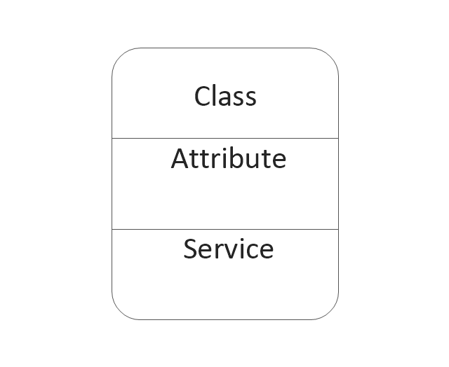
Class
Object state

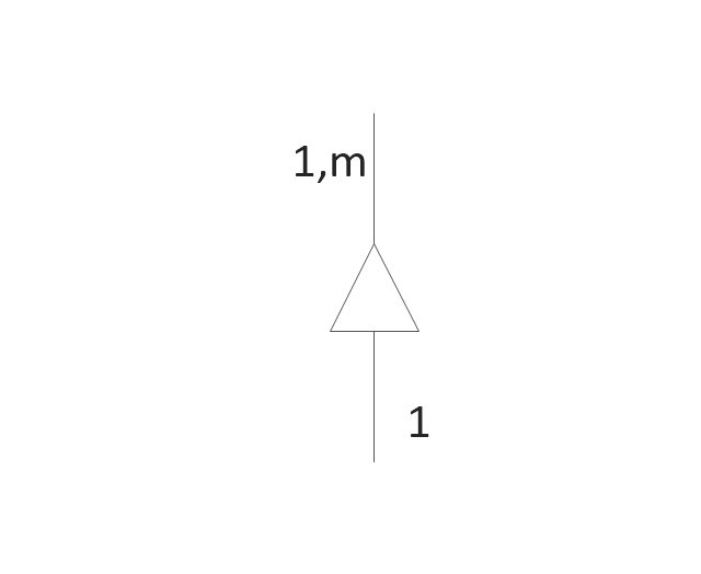
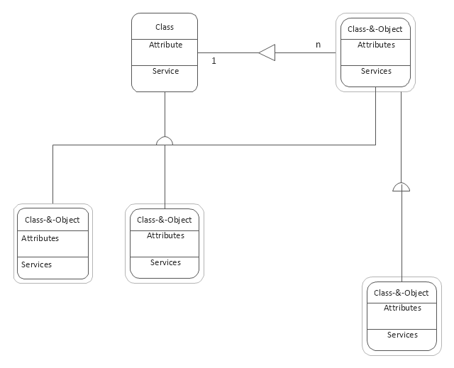
Generalization and specialization structure

Whole-part structure
Condition

Loop
External interactor
Data process
Multiple process
State
Multi-state
Stop state

Stop state2
Process
Process (offset)
-dfd,-yourdon-and-coad-notation---vector-stencils-library.png--diagram-flowchart-example.png)
Center to center

Center to center #2

Loop on center
Data store
Instance

Message

Software Diagram Examples and Templates

Software Development area of ConceptDraw Solution Park provides 5 solutions:
Data Flow Diagrams, Entity-Relationship Diagram (ERD), Graphic User Interface, IDEFO Diagrams, Rapid UML.
Yourdon and Coad Diagram

UML Class Diagram. Design Elements

Time - Design Elements

Use this template to create your DFD by Yourdon and Coad notation using the ConceptDraw PRO diagramming and vector drawing software extended with the Data Flow Diagrams solution from the Software Development area of ConceptDraw Solution Park.
DFD template
Building Drawing. Design Element — Plumbing

Object-Oriented Design

Design Element: Crows Foot for Entity Relationship Diagram - ERD

UML Class Diagrams. Diagramming Software for Design UML Diagrams

Use ConceptDraw DIAGRAM with UML class diagram templates, samples and stencil library from Rapid UML solution to show the classes of system, their attributes, operations or methods, and the relationships among the classes.

Using Both Wired and Wireless Connections

Building Networks

UML Activity Diagram. Design Elements

IDEF0 Diagram

Data Flow Diagram Symbols. DFD Library

Basic Flowchart Images. Flowchart Examples

This sample shows the Flowchart that displays the procedures of 2PP (two-party preferred) voting and counting the voters. The two-party-preferred vote is the result of the elections that was distributed to the final two parties.
Context Diagram Template

This template shows the Context Diagram. It was created in ConceptDraw DIAGRAM diagramming and vector drawing software using the Block Diagrams Solution from the “Diagrams” area of ConceptDraw Solution Park.
The context diagram graphically identifies the system. external factors, and relations between them. It’s a high level view of the system. The context diagrams are widely used in software engineering and systems engineering for designing the systems that process the information.
 Data Flow Diagrams (DFD)
Data Flow Diagrams solution extends ConceptDraw DIAGRAM software with templates, samples and libraries of vector stencils for drawing the data flow diagrams (DFD).
Data Flow Diagram (DFD)
 *")
Flowchart design. Flowchart symbols, shapes, stencils and icons

Mavericks have always desired to stand apart and gorgeous design is the recipe for that. Any business graphic document will be more understandable if will use an expository color scheme for their parts. Flowchart design makes versatile presenting and explaining of the process and gives a fresh view that distinguishes it from black and white flowcharts on a paper. Workflow diagram or process flow diagrams become more understandable to ordinary people when it use minimum symbols and special signs.
The best design can be accomplished by starting from any of the suitable Conceptdraw examples. Pick one of them and begin to input proper text into each Flowchart symbols and shapes. Apply less colors in the document and don't turn into rainbow your diagram, three or four will be enough, also note that business process flowchart may not contain bright color hues. The next clue is to use identical colors for same flowchart shape types.

- Yourdon and Coad Diagram | DFD, Yourdon and Coad notation ...
- DFD, Yourdon and Coad notation - Template
- Yourdon and Coad Diagram | ConceptDraw DIAGRAM DFD ...
- DFD, Yourdon and Coad notation - Vector stencils library | DFD ...
- DFD, Yourdon and Coad notation - Vector stencils library ...
- Yourdon and Coad Diagram | Data Flow Diagram Symbols. DFD ...
- DFD, Yourdon and Coad notation - Vector stencils library | Data ...
- DFD, Yourdon and Coad notation - Template
- DFD, Yourdon and Coad notation - Vector stencils library | Coad ...
- Data flow diagram - Template | DFD, Yourdon and Coad notation ...
- Coad / Yourdon's Object-Oriented Analysis model | ConceptDraw ...
- Coad / Yourdon's Object-Oriented Analysis model | Yourdon and ...
- Yourdon and Coad Diagram | Coad / Yourdon's Object-Oriented ...
- Yourdon and Coad Diagram | OOSE Method | Coad / Yourdon's ...
- Yourdon and Coad Diagram | OOSE Method | Professionally ...
- Booch OOD Diagram | Yourdon and Coad Diagram | Software ...
- Design elements - UML class diagrams | DFD, Yourdon and Coad ...
- DFD, Yourdon and Coad notation - Template | DFD, Gane-Sarson ...
- Booch OOD Diagram | Yourdon and Coad Diagram | Software ...
- Coad / Yourdon's Object-Oriented Analysis model | Yourdon and ...
- ERD | Entity Relationship Diagrams, ERD Software for Mac and Win
- Flowchart | Basic Flowchart Symbols and Meaning
- Flowchart | Flowchart Design - Symbols, Shapes, Stencils and Icons
- Flowchart | Flow Chart Symbols
- Electrical | Electrical Drawing - Wiring and Circuits Schematics
- Flowchart | Common Flowchart Symbols
- Flowchart | Common Flowchart Symbols