Electrical Symbols — Transmission Paths
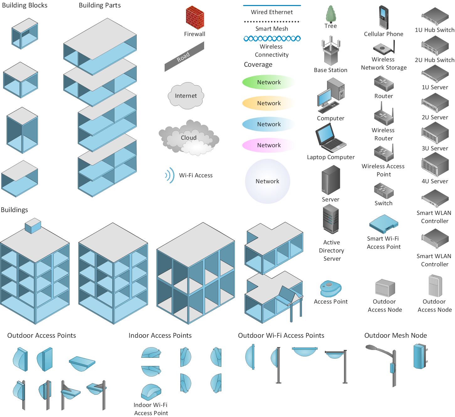
26 libraries of the Electrical Engineering Solution of ConceptDraw DIAGRAM make your electrical diagramming simple, efficient, and effective. You can simply and quickly drop the ready-to-use objects from libraries into your document to create the electrical diagram.
Cisco Network Topology. Cisco icons, shapes, stencils and symbols

Any Cisco equipment on the network are named like node. Network diagram topology commonly designed within connected nodes. Cisco icons are worldwide acknowledged and mainly established as standard icons for network diagrams. You may use them loosely, but you may not rework them.
The Cisco Network Diagram shows how signals act on the networked devices, or how data routes on the network from one device to the other. There are number of physical network typologies that engineers use while constructing computer networks.
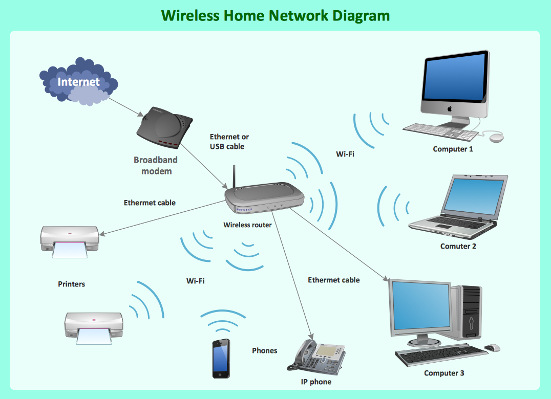
Wireless Network Mode

Wireless Networking for Mac
Cisco Routers. Cisco icons, shapes, stencils and symbols

Any planning begins with an analysis of the business requirements to the final system. Basic network parameters, which should be assessed are the scalability, accessibility, cost, speed and safety.
Speed and cost are often mistaken for the most important parameters, and the rest of the parameters aren't even remembered. This is not entirely correct. Initially, it is necessary to assess the business plans for the future, because sometimes it is more profitable to invest more money in the beginning. If the business is to develop, then, consequently, demands on
Wireless Network with ConceptDraw DIAGRAM
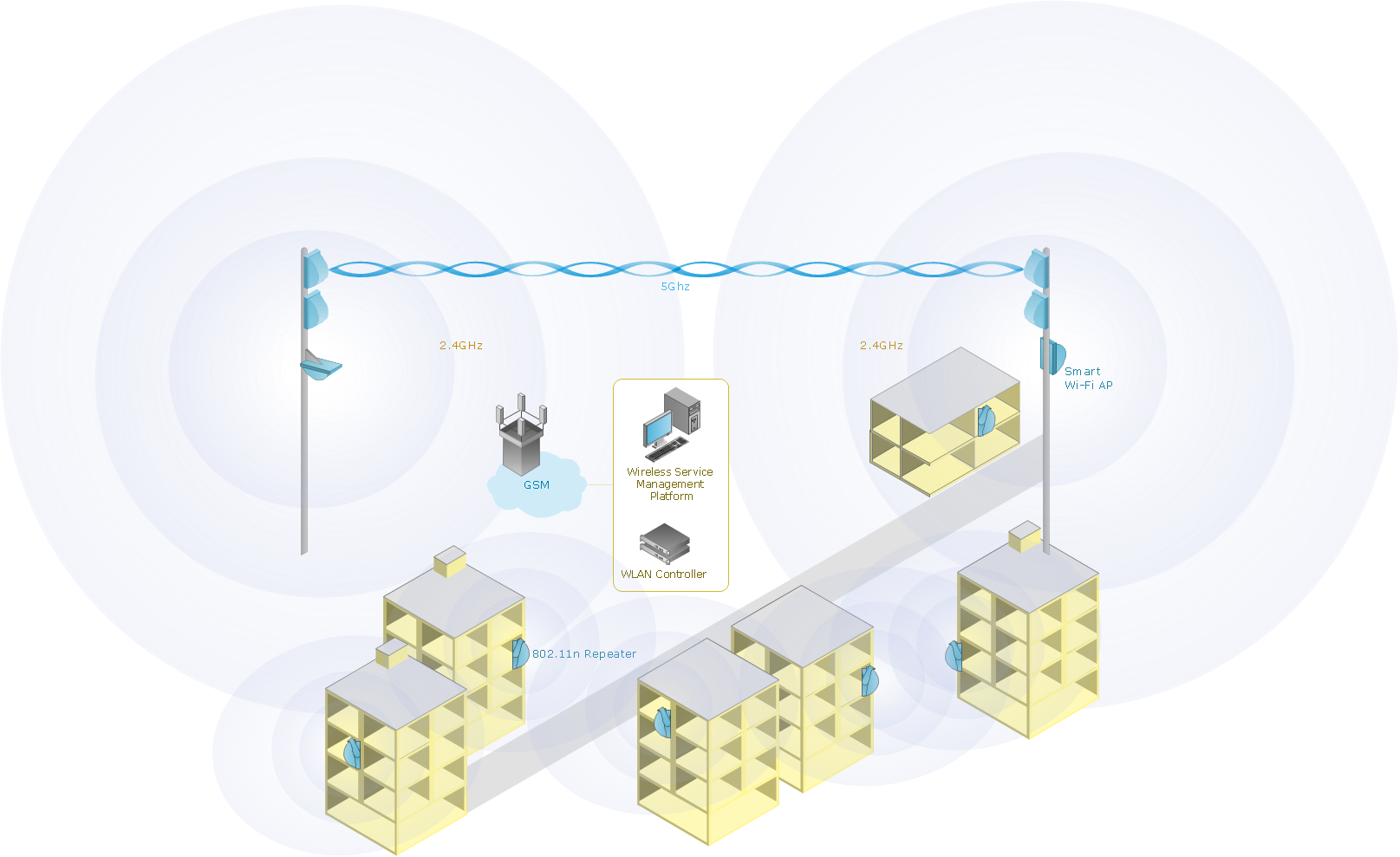
What Is a Wireless Network?
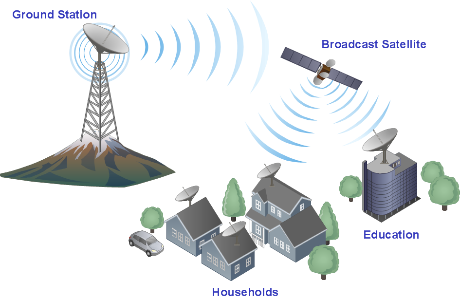
Digital Communications Network. Computer and Network Examples

This example was created in ConceptDraw DIAGRAM using the Computer and Networks Area of ConceptDraw Solution Park and shows the Digital Communication Network diagram.

Wireless Network Elements
Mesh Network Topology Diagram

The Mesh Network Topology Diagram examples was created using ConceptDraw DIAGRAM software with Computer and Networks solution.
- Cisco Network Templates | Wireless Signal Visio Stencils
- Cisco Wireless Controller Visio Stencil
- Visio Wireless Signal
- Microwave Visio Shapes
- Visio Template For Wireless Cctv Plan
- Wireless Visio Stencils
- Wifi Router Visio Stencil
- Visio Stencil Antenna Tower
- Wireless Router Stencil Visio
- How To Make MS Visio Wireless Network Diagram | Network ...
- ERD | Entity Relationship Diagrams, ERD Software for Mac and Win
- Flowchart | Basic Flowchart Symbols and Meaning
- Flowchart | Flowchart Design - Symbols, Shapes, Stencils and Icons
- Flowchart | Flow Chart Symbols
- Electrical | Electrical Drawing - Wiring and Circuits Schematics
- Flowchart | Common Flowchart Symbols
- Flowchart | Common Flowchart Symbols