Wide area network (WAN) topology. Computer and Network Examples
 topology. <br>Computer and Network Examples *")
This example was created in ConceptDraw DIAGRAM using the Computer and Networks Area of ConceptDraw Solution Park and shows the Wide area network topology.

Wide Area Work Flow

The vector stencils library "Cisco optical" contains 19 symbols of optical devices for drawing Cisco computer network diagrams.
"Fiber-optic communication is a method of transmitting information from one place to another by sending pulses of light through an optical fiber. The light forms an electromagnetic carrier wave that is modulated to carry information. ... Because of its advantages over electrical transmission, optical fibers have largely replaced copper wire communications in core networks in the developed world. Optical fiber is used by many telecommunications companies to transmit telephone signals, Internet communication, and cable television signals. ...
The process of communicating using fiber-optics involves the following basic steps: Creating the optical signal involving the use of a transmitter, relaying the signal along the fiber, ensuring that the signal does not become too distorted or weak, receiving the optical signal, and converting it into an electrical signal." [Fiber-optic communication. Wikipedia]
The symbols example "Cisco optical - Vector stencils library" was created using the ConceptDraw PRO diagramming and vector drawing software extended with the Cisco Network Diagrams solution from the Computer and Networks area of ConceptDraw Solution Park.
www.conceptdraw.com/ solution-park/ computer-networks-cisco
Automatic Protection Switching (APS)
-cisco-optical---vector-stencils-library.png--diagram-flowchart-example.png)
Channelized pipe

Concatenated payload

Optical cross-connect

WDM

Optical fiber

ONS 15104

SONET MUX

Optical amplifier

Digitall cross-connect

Optical services router

Cisco 10700

Optical transport

Wide Area Application Engine (WAE)
-cisco-optical---vector-stencils-library.png--diagram-flowchart-example.png)
Protected optical

Unprotected optical

Metro 1500

ONS 15500

Pipe

The vector stencils library "Cisco optical" contains 19 symbols of optical devices for drawing Cisco computer network diagrams.
"Fiber-optic communication is a method of transmitting information from one place to another by sending pulses of light through an optical fiber. The light forms an electromagnetic carrier wave that is modulated to carry information. ... Because of its advantages over electrical transmission, optical fibers have largely replaced copper wire communications in core networks in the developed world. Optical fiber is used by many telecommunications companies to transmit telephone signals, Internet communication, and cable television signals. ...
The process of communicating using fiber-optics involves the following basic steps: Creating the optical signal involving the use of a transmitter, relaying the signal along the fiber, ensuring that the signal does not become too distorted or weak, receiving the optical signal, and converting it into an electrical signal." [Fiber-optic communication. Wikipedia]
The symbols example "Cisco optical - Vector stencils library" was created using the ConceptDraw PRO diagramming and vector drawing software extended with the Cisco Network Diagrams solution from the Computer and Networks area of ConceptDraw Solution Park.
www.conceptdraw.com/ solution-park/ computer-networks-cisco
"Fiber-optic communication is a method of transmitting information from one place to another by sending pulses of light through an optical fiber. The light forms an electromagnetic carrier wave that is modulated to carry information. ... Because of its advantages over electrical transmission, optical fibers have largely replaced copper wire communications in core networks in the developed world. Optical fiber is used by many telecommunications companies to transmit telephone signals, Internet communication, and cable television signals. ...
The process of communicating using fiber-optics involves the following basic steps: Creating the optical signal involving the use of a transmitter, relaying the signal along the fiber, ensuring that the signal does not become too distorted or weak, receiving the optical signal, and converting it into an electrical signal." [Fiber-optic communication. Wikipedia]
The symbols example "Cisco optical - Vector stencils library" was created using the ConceptDraw PRO diagramming and vector drawing software extended with the Cisco Network Diagrams solution from the Computer and Networks area of ConceptDraw Solution Park.
www.conceptdraw.com/ solution-park/ computer-networks-cisco
Automatic Protection Switching (APS)
Channelized pipe
Concatenated payload
Optical cross-connect
WDM
Optical fiber
ONS 15104
SONET MUX
Optical amplifier
Digitall cross-connect
Optical services router
Cisco 10700
Optical transport
Wide Area Application Engine (WAE)
Protected optical
Unprotected optical
Metro 1500
ONS 15500
Pipe
The vector stencils library "American football positions" contains 38 american football (gridiron) players symbols.
Use it for drawing diagrams of American football positions in the ConceptDraw PRO diagramming and vector drawing software extended with the Football solution from the Sport area of ConceptDraw Solution Park.
Use it for drawing diagrams of American football positions in the ConceptDraw PRO diagramming and vector drawing software extended with the Football solution from the Sport area of ConceptDraw Solution Park.
Defensive tackle (DT)
-american-football-positions---vector-stencils-library.png--diagram-flowchart-example.png)
Defensive end (DE)
-american-football-positions---vector-stencils-library.png--diagram-flowchart-example.png)
Linebackers (LB)
-american-football-positions---vector-stencils-library.png--diagram-flowchart-example.png)
Cornerback (CB)
-american-football-positions---vector-stencils-library.png--diagram-flowchart-example.png)
Safety (S)
-american-football-positions---vector-stencils-library.png--diagram-flowchart-example.png)
Quarterback (QB)
-american-football-positions---vector-stencils-library.png--diagram-flowchart-example.png)
Running back (RB)
-american-football-positions---vector-stencils-library.png--diagram-flowchart-example.png)
Wide receiver (WR)
-american-football-positions---vector-stencils-library.png--diagram-flowchart-example.png)
Tight end (TE)
-american-football-positions---vector-stencils-library.png--diagram-flowchart-example.png)
Center (C)
-american-football-positions---vector-stencils-library.png--diagram-flowchart-example.png)
Offensive guard (G)
-american-football-positions---vector-stencils-library.png--diagram-flowchart-example.png)
Offensive tackle (T)
-american-football-positions---vector-stencils-library.png--diagram-flowchart-example.png)
Kicker (K)
-american-football-positions---vector-stencils-library.png--diagram-flowchart-example.png)
Holder (H)
-american-football-positions---vector-stencils-library.png--diagram-flowchart-example.png)
Long snapper (LS)
-american-football-positions---vector-stencils-library.png--diagram-flowchart-example.png)
Punter (P)
-american-football-positions---vector-stencils-library.png--diagram-flowchart-example.png)
Kickoff specialist (KOS)
-american-football-positions---vector-stencils-library.png--diagram-flowchart-example.png)
Punt returner (PR)
-american-football-positions---vector-stencils-library.png--diagram-flowchart-example.png)
Kick returner (KR)
-american-football-positions---vector-stencils-library.png--diagram-flowchart-example.png)
Defensive tackle (DT)
-american-football-positions---vector-stencils-library.png--diagram-flowchart-example.png)
Defensive end (DE)
-american-football-positions---vector-stencils-library.png--diagram-flowchart-example.png)
Linebackers (LB)
-american-football-positions---vector-stencils-library.png--diagram-flowchart-example.png)
Cornerback (CB)
-american-football-positions---vector-stencils-library.png--diagram-flowchart-example.png)
Safety (S)
-american-football-positions---vector-stencils-library.png--diagram-flowchart-example.png)
Quarterback (QB)
-american-football-positions---vector-stencils-library.png--diagram-flowchart-example.png)
Running back (RB)
-american-football-positions---vector-stencils-library.png--diagram-flowchart-example.png)
Wide receiver (WR)
-american-football-positions---vector-stencils-library.png--diagram-flowchart-example.png)
Tight end (TE)
-american-football-positions---vector-stencils-library.png--diagram-flowchart-example.png)
Center (C)
-american-football-positions---vector-stencils-library.png--diagram-flowchart-example.png)
Guard (G)
-american-football-positions---vector-stencils-library.png--diagram-flowchart-example.png)
Tackle (T)
-american-football-positions---vector-stencils-library.png--diagram-flowchart-example.png)
Kicker (K)
-american-football-positions---vector-stencils-library.png--diagram-flowchart-example.png)
Holder (H)
-american-football-positions---vector-stencils-library.png--diagram-flowchart-example.png)
Long snapper (LS)
-american-football-positions---vector-stencils-library.png--diagram-flowchart-example.png)
Punter (P)
-american-football-positions---vector-stencils-library.png--diagram-flowchart-example.png)
Kickoff specialist (KOS)
-american-football-positions---vector-stencils-library.png--diagram-flowchart-example.png)
Punt returner (PR)
-american-football-positions---vector-stencils-library.png--diagram-flowchart-example.png)
Kick returner (KR)
-american-football-positions---vector-stencils-library.png--diagram-flowchart-example.png)
The vector stencils library "American football positions" contains 38 american football (gridiron) players symbols.
Use it for drawing diagrams of American football positions in the ConceptDraw PRO diagramming and vector drawing software extended with the Football solution from the Sport area of ConceptDraw Solution Park.
Use it for drawing diagrams of American football positions in the ConceptDraw PRO diagramming and vector drawing software extended with the Football solution from the Sport area of ConceptDraw Solution Park.
Defensive tackle (DT)
Defensive end (DE)
Linebackers (LB)
Cornerback (CB)
Safety (S)
Quarterback (QB)
Running back (RB)
Wide receiver (WR)
Tight end (TE)
Center (C)
Offensive guard (G)
Offensive tackle (T)
Kicker (K)
Holder (H)
Long snapper (LS)
Punter (P)
Kickoff specialist (KOS)
Punt returner (PR)
Kick returner (KR)
Defensive tackle (DT)
Defensive end (DE)
Linebackers (LB)
Cornerback (CB)
Safety (S)
Quarterback (QB)
Running back (RB)
Wide receiver (WR)
Tight end (TE)
Center (C)
Guard (G)
Tackle (T)
Kicker (K)
Holder (H)
Long snapper (LS)
Punter (P)
Kickoff specialist (KOS)
Punt returner (PR)
Kick returner (KR)
This sport field plan sample was designed on the base of the Wikipedia file: VolleyballCourt.svg. [en.wikipedia.org/ wiki/ File:VolleyballCourt.svg]
This file is licensed under the Creative Commons Attribution-Share Alike 3.0 Unported license. [creativecommons.org/ licenses/ by-sa/ 3.0/ deed.en]
"Volleyball is a team sport in which two teams of six players are separated by a net. Each team tries to score points by grounding a ball on the other team's court under organized rules. It has been a part of the official program of the Summer Olympic Games since 1964. ...
The court dimensions.
A volleyball court is 18 m (59 ft) long and 9 m (29.5 ft) wide, divided into 9 m × 9 m halves by a one-meter (40-inch) wide net. The top of the net is 2.43 m (8 ft 0 in) above the center of the court for men's competition, and 2.24 m (7 ft 4 in) for women's competition, varied for veterans and junior competitions.
The minimum height clearance for indoor volleyball courts is 7 m (23 ft), although a clearance of 8 m (26 ft) is recommended.
A line 3 m (9.84 ft) from and parallel to the net is considered the "attack line". This "3 meter" (or "10-foot") line divides the court into "back row" and "front row" areas (also back court and front court). These are in turn divided into 3 areas each: these are numbered as follows, starting from area "1", which is the position of the serving player.
After a team gains the serve (also known as siding out), its members must rotate in a clockwise direction, with the player previously in area "2" moving to area "1" and so on, with the player from area "1" moving to area "6".
The team courts are surrounded by an area called the free zone which is a minimum of 3 meters wide and which the players may enter and play within after the service of the ball. All lines denoting the boundaries of the team court and the attack zone are drawn or painted within the dimensions of the area and are therefore a part of the court or zone. If a ball comes in contact with the line, the ball is considered to be "in". An antenna is placed on each side of the net perpendicular to the sideline and is a vertical extension of the side boundary of the court. A ball passing over the net must pass completely between the antennae (or their theoretical extensions to the ceiling) without contacting them." [Volleyball. Wikipedia]
The sport field plan example "Volleyball court dimensions" was created using the ConceptDraw PRO diagramming and vector drawing software extended with the Sport Field Plans solution from the Building Plans area of ConceptDraw Solution Park.
Sport field plan

"In association football, the formation describes how the players in a team are positioned on the pitch. Different formations can be used depending on whether a team wishes to play more attacking or defensive football. ...
4–4–2.
This formation was the most common in football in the 1990s and early 2000s, so well known that it has even inspired a magazine title, FourFourTwo. The midfielders are required to work hard to support both the defence and the attack: typically one of the central midfielders is expected to go upfield as often as possible to support the forward pair, while the other will play a "holding role", shielding the defence; the two wide midfield players must move up the flanks to the goal line in attacks and yet also protect the fullback wide defenders." [Formation (association football). Wikipedia]
The diagram example "Association football (soccer) formation 4-4-2" was created using the ConceptDraw PRO diagramming and vector drawing software extended with the Football solution from the Sport area of ConceptDraw Solution Park.
www.conceptdraw.com/ solution-park/ sport-soccer
Association football (soccer) formation diagram
-formation-diagram-association-football-(soccer)-formation-4-4-2.png--diagram-flowchart-example.png)
The vector stencils library "Cisco LAN" contains 23 symbols of local area network (LAN) devices and equipment for drawing Cisco LAN topology diagrams.
"Network topology describes the layout of interconnections between devices and network segments. At the Data Link Layer and Physical Layer, a wide variety of LAN topologies have been used, including ring, bus, mesh and star, but the most common LAN topology in use today is switched Ethernet. At the higher layers, the Internet Protocol (TCP/ IP) has become the standard, replacing NetBEUI, IPX/ SPX, AppleTalk and others.
Simple LANs generally consist of one or more switches. A switch can be connected to a router, cable modem, or ADSL modem for Internet access. Complex LANs are characterized by their use of redundant links with switches using the spanning tree protocol to prevent loops, their ability to manage differing traffic types via quality of service (QoS), and to segregate traffic with VLANs. A LAN can include a wide variety of network devices such as switches, firewalls, routers, load balancers, and sensors.
LANs can maintain connections with other LANs via leased lines, leased services, or the Internet using virtual private network technologies. Depending on how the connections are established and secured in a LAN, and the distance involved, a LAN may also be classified as a metropolitan area network (MAN) or a wide area network (WAN)." [Local area network. Wikipedia]
The symbols example "Cisco LAN - Vector stencils library" was created using the ConceptDraw PRO diagramming and vector drawing software extended with the Cisco Network Diagrams solution from the Computer and Networks area of ConceptDraw Solution Park.
www.conceptdraw.com/ solution-park/ computer-networks-cisco
Sun workstation

Workstation

PC

Macintosh

Terminal

Mini VAX

Printer

Laptop

File server

Monitor

Web cluster

ATM fast gigabit etherswitch

HP Mini

Supercomputer

LAN2LAN

LAN to LAN

Web server

Web browser

Repeater

PDA

General appliance

PC, blue

Mini VAX, blue

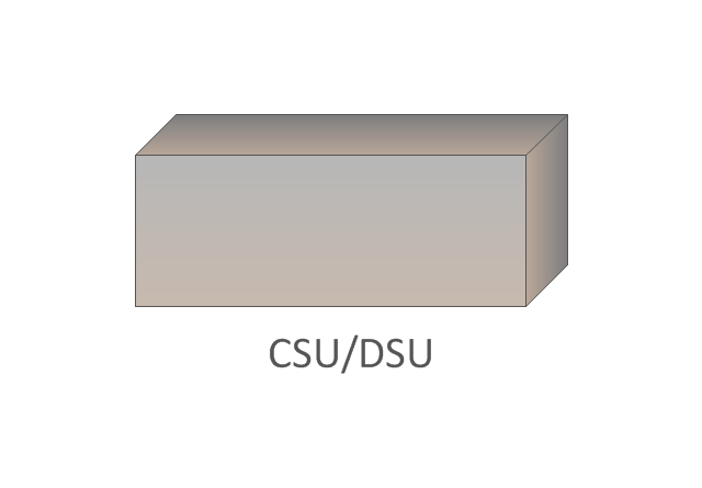
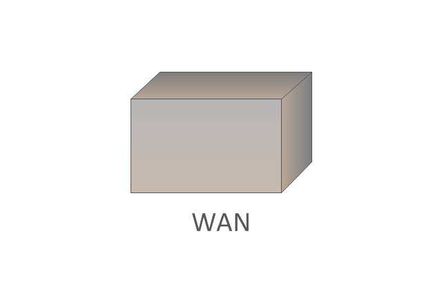
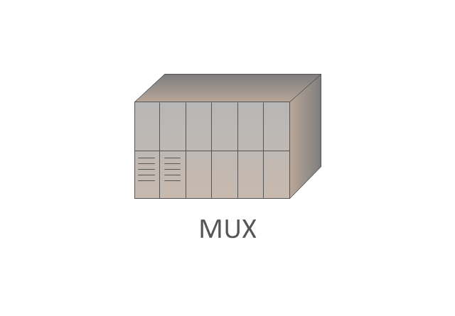
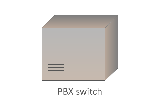
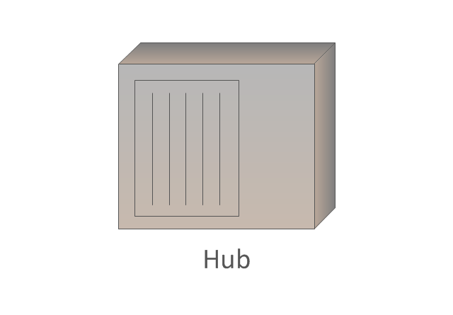
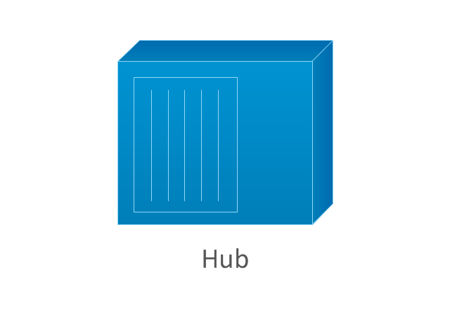
The vector stencils library "Cisco WAN" contains 15 symbols of wide area network (WAN) devices and equipment: CSU/ DSU (Channel Service Unit/ Data Service Unit), WAN, MUX (multiplexer), PBX switch, Hub, NAT (network address translation), distributed and local directors, PBX (private branch exchange), Network clouds, DPT (dynamic packet transport).
Create the computer network topology diagrams using the ConceptDraw PRO diagramming and vector drawing software with the design elements library "Cisco WAN".
"A wide area network (WAN) is a network that covers a broad area (i.e., any telecommunications network that links across metropolitan, regional, or national boundaries) using private or public network transports. Business and government entities utilize WANs to relay data among employees, clients, buyers, and suppliers from various geographical locations. In essence, this mode of telecommunication allows a business to effectively carry out its daily function regardless of location. The Internet can be considered a WAN as well, and is used by businesses, governments, organizations, and individuals for almost any purpose imaginable.
Related terms for other types of networks are personal area networks (PANs), local area networks (LANs), campus area networks (CANs), or metropolitan area networks (MANs) which are usually limited to a room, building, campus or specific metropolitan area (e.g., a city) respectively." [Wide area network. Wikipedia]
The example "Design elements - Cisco WAN" is included in the Cisco Network Diagrams solution from the Computer and Networks area of ConceptDraw Solution Park.
Cisco WAN symbols
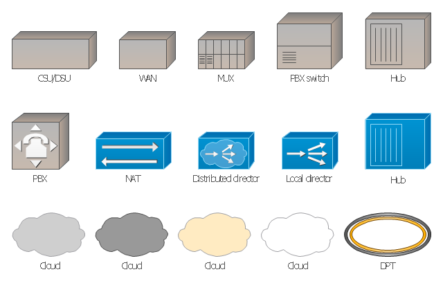
The vector stencils library "Cisco WAN" contains 15 symbols of wide area network (WAN) devices and equipment for drawing Cisco WAN diagrams.
"A wide area network (WAN) is a network that covers a broad area (i.e., any telecommunications network that links across metropolitan, regional, or national boundaries) using leased telecommunication lines. Business and government entities utilize WANs to relay data among employees, clients, buyers, and suppliers from various geographical locations. ...
Related terms for other types of networks are personal area networks (PANs), local area networks (LANs), campus area networks (CANs), or metropolitan area networks (MANs) which are usually limited to a room, building, campus or specific metropolitan area (e.g., a city) respectively.
... it may be best to view WANs as computer networking technologies used to transmit data over long distances, and between different LANs, MANs and other localised computer networking architectures. ...
WANs are often built using leased lines. At each end of the leased line, a router connects the LAN on one side with a second router within the LAN on the other. Leased lines can be very expensive. Instead of using leased lines, WANs can also be built using less costly circuit switching or packet switching methods. Network protocols including TCP/ IP deliver transport and addressing functions. Protocols including Packet over SONET/ SDH, MPLS, ATM and Frame relay are often used by service providers to deliver the links that are used in WANs." [Wide area network. Wikipedia]
The symbols example "Cisco WAN - Vector stencils library" was created using the ConceptDraw PRO diagramming and vector drawing software extended with the Cisco Network Diagrams solution from the Computer and Networks area of ConceptDraw Solution Park.
www.conceptdraw.com/ solution-park/ computer-networks-cisco
CSU/DSU
WAN
MUX
PBX switch
Hub
Hub, blue
NAT

Network cloud, dark
Network cloud, gold
Network cloud, white
Network cloud, standard color
Distributed director
Local director
PBX
DPT
"In association football, the formation describes how the players in a team are positioned on the pitch. Different formations can be used depending on whether a team wishes to play more attacking or defensive football. ...
The 4–3–3 was a development of the 4–2–4, and was played by the Brazilian national team in the 1962 World Cup. The extra player in midfield allows a stronger defence, and the midfield could be staggered for different effects. The three midfielders normally play closely together to protect the defence, and move laterally across the field as a coordinated unit. The three forwards split across the field to spread the attack, and may be expected to mark the opposition full-backs as opposed to doubling back to assist their own full-backs, as do the wide midfielders in a 4–4–2. When used from the start of a game, this formation is widely regarded as encouraging expansive play, and should not be confused with the practice of modifying a 4–4–2 by bringing on an extra forward to replace a midfield player when behind in the latter stages of a game. This formation is suited for a short passing game and useful for ball retention.
A staggered 4–3–3 involving a defensive midfielder (usually numbered four or six) and two attacking midfielders (numbered eight and ten) was commonplace in Italy, Argentina, and Uruguay during the 1960s and 1970s. The Italian variety of 4–3–3 was simply a modification of WM, by converting one of the two wing-halves to a libero (sweeper), whereas the Argentine and Uruguayan formations were derived from 2–3–5 and retained the notional attacking centre-half. The national team which made this famous was the Dutch team of the 1974 and 1978 World Cups, even though the team won neither." [Formation (association football). Wikipedia]
The diagram example "Association football (soccer) formation 4-3-3" was created using the ConceptDraw PRO diagramming and vector drawing software extended with the Football solution from the Sport area of ConceptDraw Solution Park.
www.conceptdraw.com/ solution-park/ sport-soccer
Association football (soccer) formation diagram
-formation-diagram-association-football-(soccer)-formation-4-3-3.png--diagram-flowchart-example.png)
"Offensive tactics in set pieces. ...
Throw-ins[edit]
How throw-ins are best handled depends on where it is:
(1) In one's own half the aim of a throw-in may be to retain possession in order to build up the next attack. The throw may or may not go toward the opponents' goal; the most unmarked player may be a full-back who is behind the ball. Such a throw followed by a quickly taken 'switch' pass can be an effective tactic. Under pressure however, the ball is often thrown up the line, toward the opponents' goal line to gain as much ground as possible.
(2) If the thrower is unmarked, a simple tactic is to take a short throw to the feet or chest of a marked player who immediately returns the ball to the thrower.
(3) In the last third of the pitch a player with a long throw can put pressure onto the defenders by throwing the ball deep into the opponents' penalty area, resulting in somewhat similar tactics to a corner kick situation, but with the added advantage of avoiding the offside trap, as an attacking player cannot be offside from a throw in. ...
Goal kicks.
A goal kick is an important 'set piece' that will occur many times in a game and yet few teams practice it. If taken quickly the kick may be taken short to a full-back who has run into a wide position. Although this may gain little ground it retains the all-important possession of the ball. A longer kick to the midfield is more common and it is vital that the midfield unit are in a position to receive it.
Corners.
A corner kick (or "corner") is a real goal scoring opportunity and it is essential to know who is the best at taking a good corner from both the left and right side of the pitch. A good corner will be aimed high across the goal and may be 'bent' towards or away from the goal. At least one of the forwards should be on or close to the goal line when the kick is taken.
Another tactic on a corner is to let the best shooter stay in the back "trash" position and have the defence worried about those up front. The player taking the corner kick makes a small pass back to the trash shooter who has time and space to take a good shot." [Association football tactics and skills. Wikipedia]
The diagram example "Association football (soccer) - The pitch: throw-ins, goal kicks, corners" was created using the ConceptDraw PRO diagramming and vector drawing software extended with the Football solution from the Sport area of ConceptDraw Solution Park.
www.conceptdraw.com/ solution-park/ sport-soccer
Association football (soccer) tactics diagram
-tactics-diagram-association-football-(soccer)---the-pitch:-throw-ins,-goal-kicks,-corners.png--diagram-flowchart-example.png)
"In American football, the pro set or split backs formation is a formation that was commonly used as a "base" set by professional and amateur teams. The "pro set" formation featured a backfield that deployed two running backs aligned side-by-side instead of one in front of the other as in traditional I-formation sets. It was an outgrowth of the original, three running back T-formation, with the third back (one of the halfbacks) in the T becoming a permanent flanker, now referred to as a wide receiver. ...
A common variant of this formation removes the tight end and replaces it with a third receiver in the "slot" position. The formation is utilized to remove a defensive player from the tackle box to give the offense a 7-on-6 matchup.
There are three formations in the pro set of forms: Pro, Ace, and Tree." [Pro set. Wikipedia]
The American football positions diagram example "Pro set formation (Offense)" was created using the ConceptDraw PRO diagramming and vector drawing software extended with the Football solution from the Sport area of ConceptDraw Solution Park.
American football positions diagram
.png--diagram-flowchart-example.png)
Network Engineering

Network Diagram Software Home Area Network

"The I formation is one of the most common offensive formations in American football. The I formation draws its name from the vertical (as viewed from the opposing endzone) alignment of quarterback, fullback, and running back, particularly when contrasted with the same players' alignments in the T formation.
The formation begins with the usual 5 offensive linemen (2 offensive tackles, 2 guards, and a center), the quarterback under center, and two backs in-line behind the quarterback. The base variant adds a tight end to one side of the line and two wide receivers, one at each end of the line." [I formation. Wikipedia]
The American football positions diagram example "I Formation (Offense)" was created using the ConceptDraw PRO diagramming and vector drawing software extended with the Football solution from the Sport area of ConceptDraw Solution Park.
American football positions diagram
.png--diagram-flowchart-example.png)
Cisco WAN. Cisco icons, shapes, stencils and symbols

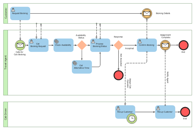
This BPMN (Business Process Model and Notation) collaboration diagram sample depicts interactions between customer, travel agent and cab driver, which are defined as a sequence of activities, and represent the message exchange during a cab booking process.
"Business process modeling is used to communicate a wide variety of information to a wide variety of audiences. BPMN is designed to cover this wide range of usage and allows modeling of end-to-end business processes to allow the viewer of the Diagram to be able to easily differentiate between sections of a BPMN Diagram. There are three basic types of sub-models within an end-to-end BPMN model: Private (internal) business processes, Abstract (public) processes, and Collaboration (global) processes...
Collaboration (global) processes.
A collaboration process depicts the interactions between two or more business entities. These interactions are defined as a sequence of activities that represent the message exchange patterns between the entities involved. Collaboration processes may be contained within a Pool and the different participant business interactions are shown as Lanes within the Pool. In this situation, each Lane would represent two participants and a direction of travel between them. They may also be shown as two or more Abstract Processes interacting through Message Flow. These processes can be modeled separately or within a larger BPMN Diagram to show the Associations between the collaboration process activities and other entities. If the collaboration process is in the same Diagram as one of its corresponding private business process, then the activities that are common to both processes can be associated." [Business Process Model and Notation. Wikipedia]
The business process modeling diagram example "Cab booking public process - Collaboration BPMN 2.0 diagram" was designed using the ConceptDraw PRO diagramming and vector drawing software extended with the Business Process Diagram solution from the Business Processes area of ConceptDraw Solution Park.
Business process modeling
Examples of Flowcharts, Org Charts and More


- Wide area network (WAN) topology. Computer and Network ...
- Wide area network (WAN) topology. Computer and Network Examples
- Bus Network Topology | Tree Network Topology Diagram | Wide ...
- Metropolitan area networks (MAN). Computer and Network ...
- Wide Area Network Diagram Examples
- Wireless Network Topology | Wide area network (WAN) topology ...
- Bus Network Topology | Wide area network (WAN) topology ...
- Tree Network Topology Diagram | Wide area network (WAN ...
- AWS | Telecommunication Network Diagrams | Wide area network ...
- Cisco optical - Vector stencils library
- Network Diagram Software | Network Diagram Examples | Wide ...
- Design elements - Cisco WAN | Cisco Network Templates | Wide ...
- Campus Area Networks (CAN). Computer and Network Examples ...
- Design elements - Video and audio | Server | Wide area network ...
- Wide Area Application Engine (WAE)
- Physical network. Computer and Network Examples | Wide area ...
- American football positions - Vector stencils library
- Wide Are Network Diagam Function
- Examples of Flowcharts, Org Charts and More | Wide area network ...
- Metropolitan area networks (MAN). Computer and Network Examples
- ERD | Entity Relationship Diagrams, ERD Software for Mac and Win
- Flowchart | Basic Flowchart Symbols and Meaning
- Flowchart | Flowchart Design - Symbols, Shapes, Stencils and Icons
- Flowchart | Flow Chart Symbols
- Electrical | Electrical Drawing - Wiring and Circuits Schematics
- Flowchart | Common Flowchart Symbols
- Flowchart | Common Flowchart Symbols