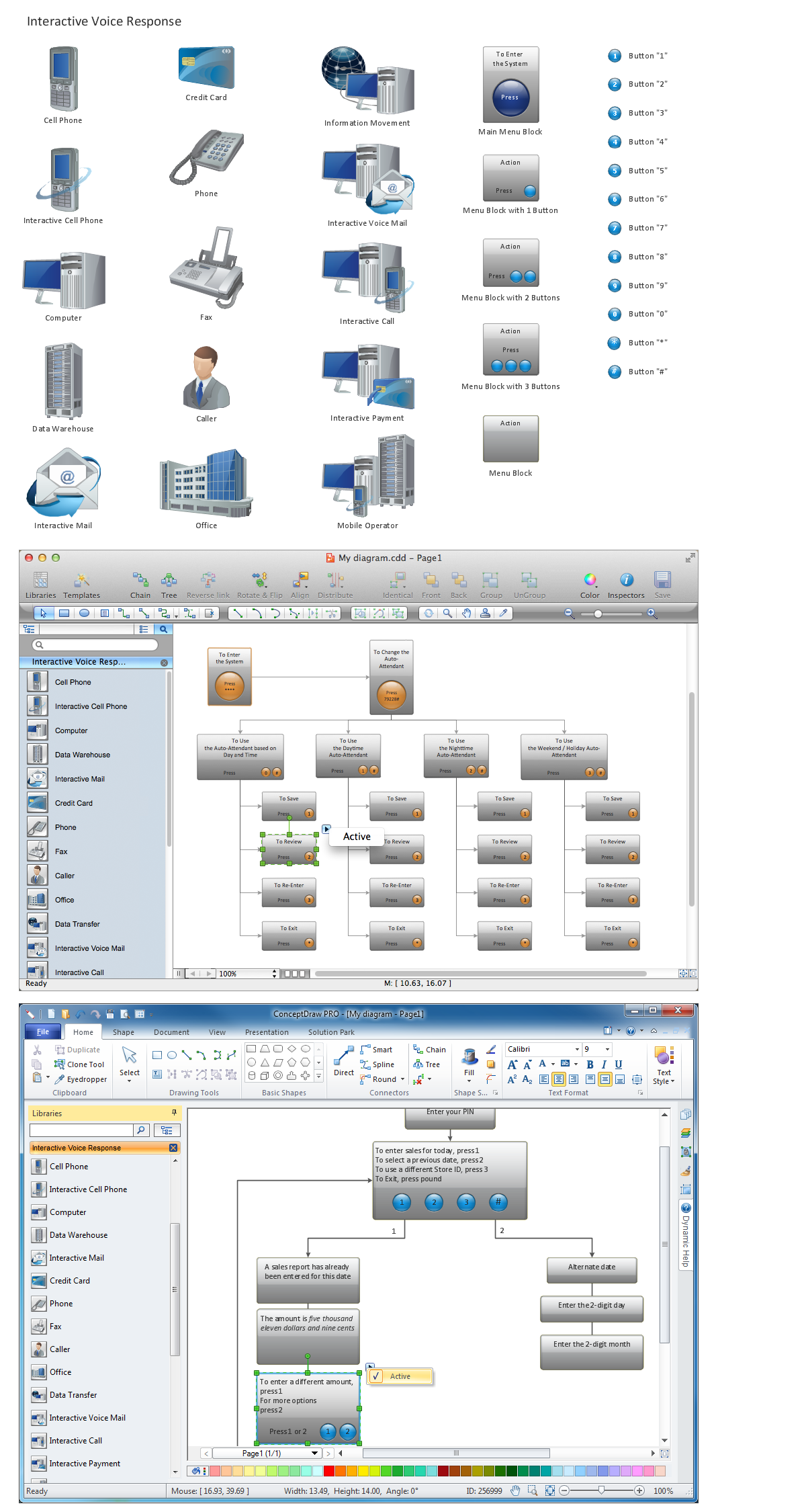
Network Diagramming Software for Design IVR Network Diagrams

 Computer and Networks Area
The solutions from Computer and Networks Area of ConceptDraw Solution Park collect samples, templates and vector stencils libraries for drawing computer and network diagrams, schemes and technical drawings.
 Computer Network Diagrams
Computer Network Diagrams solution extends ConceptDraw DIAGRAM software with samples, templates and libraries of vector icons and objects of computer network devices and network components to help you create professional-looking Computer Network Diagrams, to plan simple home networks and complex computer network configurations for large buildings, to represent their schemes in a comprehensible graphical view, to document computer networks configurations, to depict the interactions between network's components, the used protocols and topologies, to represent physical and logical network structures, to compare visually different topologies and to depict their combinations, to represent in details the network structure with help of schemes, to study and analyze the network configurations, to communicate effectively to engineers, stakeholders and end-users, to track network working and troubleshoot, if necessary.
IDEF9 Standard

HelpDesk
How to Create a Bank ATM Use Case Diagram

ConceptDraw DIAGRAM diagramming software, enhanced and expanded with the ATM UML Diagrams solution, offers the full range of icons, templates and design elements needed to faithfully represent ATM and banking information system architecture using UML standards. The ATM UML Diagrams solution is useful for beginner and advanced users alike. More experienced users will appreciate a full range of vector stencil libraries and ConceptDraw DIAGRAM's powerful software, that allows you to create your ATM UML diagram in a matter of moments.
HelpDesk
How To Add a Computer Network Diagram to a PowerPoint Presentation

 ConceptDraw Solution Park
ConceptDraw Solution Park collects graphic extensions, examples and learning materials
Software development with ConceptDraw DIAGRAM

 Network Layout Floor Plans
Network Layout Floor Plans solution extends ConceptDraw DIAGRAM software functionality with powerful tools for quick and efficient documentation the network equipment and displaying its location on the professionally designed Network Layout Floor Plans. Never before creation of Network Layout Floor Plans, Network Communication Plans, Network Topologies Plans and Network Topology Maps was not so easy, convenient and fast as with predesigned templates, samples, examples and comprehensive set of vector design elements included to the Network Layout Floor Plans solution. All listed types of plans will be a good support for the future correct cabling and installation of network equipment.
- Network Topologies | UML Notation | Design Element: IVR for ...
- Atm Network Diagram
- Network diagrams with ConceptDraw PRO | Network Topologies ...
- Network Diagram Software Physical Network Diagram | Star ...
- UML Diagram Types List | UML Diagram | UML Notation | Software ...
- ATM Network. Computer and Network Examples | ATM UML ...
- ATM Network. Computer and Network Examples | Network ...
- UML Diagram Types List | UML Diagrams with ConceptDraw PRO ...
- UML Class Diagrams . Diagramming Software for Design UML ...
- Diagram Physical Topologies | Network Diagram Software Physical ...
- Design Element: IVR for Network Diagrams | Computer and ...
- Computer Network Diagrams | Telecommunication Network ...
- Diagramming Software for Design UML Communication Diagrams ...
- UML Class Diagram Example - Medical Shop | UML Notation | How ...
- ATM UML Diagrams | Banking System | Bank UML Diagram ...
- Data Flow Diagrams (DFD) | DFD Library System | UML Diagram ...
- ATM UML Diagrams | How to Create a Bank ATM Use Case ...
- Entity-Relationship Diagram (ERD) | Computer Network Diagrams ...
- UML Diagram Types List | Basic Diagramming | Program Evaluation ...
- Computer Network Diagrams | Computer Networking Tools List ...
- ERD | Entity Relationship Diagrams, ERD Software for Mac and Win
- Flowchart | Basic Flowchart Symbols and Meaning
- Flowchart | Flowchart Design - Symbols, Shapes, Stencils and Icons
- Flowchart | Flow Chart Symbols
- Electrical | Electrical Drawing - Wiring and Circuits Schematics
- Flowchart | Common Flowchart Symbols
- Flowchart | Common Flowchart Symbols