The vector stencils library "Bank UML sequence diagram" contains 34 shapes for drawing UML sequence diagrams.
Use it for object-oriented modeling of your bank information system.
"A sequence diagram shows, as parallel vertical lines (lifelines), different processes or objects that live simultaneously, and, as horizontal arrows, the messages exchanged between them, in the order in which they occur. This allows the specification of simple runtime scenarios in a graphical manner.
Diagram building blocks.
If the lifeline is that of an object, it demonstrates a role. Leaving the instance name blank can represent anonymous and unnamed instances.
Messages, written with horizontal arrows with the message name written above them, display interaction. Solid arrow heads represent synchronous calls, open arrow heads represent asynchronous messages, and dashed lines represent reply messages. ...
Activation boxes, or method-call boxes, are opaque rectangles drawn on top of lifelines to represent that processes are being performed in response to the message (ExecutionSpecifications in UML).
Objects calling methods on themselves use messages and add new activation boxes on top of any others to indicate a further level of processing.
When an object is destroyed (removed from memory), an X is drawn on top of the lifeline, and the dashed line ceases to be drawn below it ...
A message sent from outside the diagram can be represented by a message originating from a filled-in circle (found message in UML) or from a border of the sequence diagram (gate in UML)." [Sequence diagram. Wikipedia]
This example of UML sequence diagram symbols for the ConceptDraw PRO diagramming and vector drawing software is included in the ATM UML Diagrams solution from the Software Development area of ConceptDraw Solution Park.
UML sequence diagram symbols

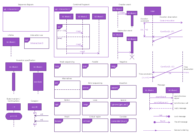
The vector stencils library "Sequence diagram" contains 32 SysML symbols.
Use it to design your sequence diagrams using ConceptDraw PRO diagramming and vector drawing software.
"A sequence diagram shows, as parallel vertical lines (lifelines), different processes or objects that live simultaneously, and, as horizontal arrows, the messages exchanged between them, in the order in which they occur. This allows the specification of simple runtime scenarios in a graphical manner. ...
If the lifeline is that of an object, it demonstrates a role. Leaving the instance name blank can represent anonymous and unnamed instances.
Messages, written with horizontal arrows with the message name written above them, display interaction. Solid arrow heads represent synchronous calls, open arrow heads represent asynchronous messages, and dashed lines represent reply messages. If a caller sends a synchronous message, it must wait until the message is done, such as invoking a subroutine. If a caller sends an asynchronous message, it can continue processing and doesn’t have to wait for a response. Asynchronous calls are present in multithreaded applications and in message-oriented middleware. Activation boxes, or method-call boxes, are opaque rectangles drawn on top of lifelines to represent that processes are being performed in response to the message (ExecutionSpecifications in UML).
Objects calling methods on themselves use messages and add new activation boxes on top of any others to indicate a further level of processing.
When an object is destroyed (removed from memory), an X is drawn on top of the lifeline, and the dashed line ceases to be drawn below it (this is not the case in the first example though). It should be the result of a message, either from the object itself, or another.
A message sent from outside the diagram can be represented by a message originating from a filled-in circle (found message in UML) or from a border of the sequence diagram (gate in UML)." [Sequence diagram. Wikipedia]
The SysML shapes example "Design elements - Sequence diagram" is included in the SysML solution from the Software Development area of ConceptDraw Solution Park.
SysML sequence diagram symbols
IDEF3 Standard

 Business Process Diagrams
Business Process Diagrams solution extends the ConceptDraw PRO BPM software with RapidDraw interface, templates, samples and numerous libraries based on the BPMN 1.2 and BPMN 2.0 standards, which give you the possibility to visualize equally easy simple and complex processes, to design business models, to quickly develop and document in details any business processes on the stages of project’s planning and implementation.
The vector stencils library "UML sequence diagrams" contains 50 symbols for the ConceptDraw PRO diagramming and vector drawing software.
"Sequence diagram ... building blocks.
If the lifeline is that of an object, it demonstrates a role. Note that leaving the instance name blank can represent anonymous and unnamed instances.
Messages, written with horizontal arrows with the message name written above them, display interaction. Solid arrow heads represent synchronous calls, open arrow heads represent asynchronous messages, and dashed lines represent reply messages. If a caller sends a synchronous message, it must wait until the message is done, such as invoking a subroutine. If a caller sends an asynchronous message, it can continue processing and doesn’t have to wait for a response. Asynchronous calls are present in multithreaded applications and in message-oriented middleware. Activation boxes, or method-call boxes, are opaque rectangles drawn on top of lifelines to represent that processes are being performed in response to the message (ExecutionSpecifications in UML).
Objects calling methods on themselves use messages and add new activation boxes on top of any others to indicate a further level of processing.
When an object is destroyed (removed from memory), an X is drawn on top of the lifeline, and the dashed line ceases to be drawn below it (this is not the case in the first example though). It should be the result of a message, either from the object itself, or another.
A message sent from outside the diagram can be represented by a message originating from a filled-in circle (found message in UML) or from a border of the sequence diagram (gate in UML)." [Sequence diagram. Wikipedia]
The example "Design elements - UML sequence diagrams" is included in the Rapid UML solution from the Software Development area of ConceptDraw Solution Park.
UML sequence diagram symbols

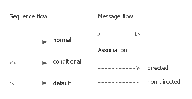
The vector stencils library "Connections BPMN1.2" contains 6 connection symbols of sequence flow, message flow, and association.
Use these shapes for drawing business process diagrams (BPMN 1.2) using the ConceptDraw PRO diagramming and vector drawing software.
"Connections.
Flow objects are connected to each other using Connecting objects, which are of three types: sequences, messages, and associations.
(1) Sequence Flow.
A Sequence Flow is represented with a solid line and arrowhead, and shows in which order the activities are performed. The sequence flow may also have a symbol at its start, a small diamond indicates one of a number of conditional flows from an activity, while a diagonal slash indicates the default flow from a decision or activity with conditional flows.
(2) Message Flow.
A Message Flow is represented with a dashed line, an open circle at the start, and an open arrowhead at the end. It tells us what messages flow across organizational boundaries (i.e., between pools). A message flow can never be used to connect activities or events within the same pool.
(3) Association.
An Association is represented with a dotted line. It is used to associate an Artifact or text to a Flow Object, and can indicate some directionality using an open arrowhead (toward the artifact to represent a result, from the artifact to represent an input, and both to indicate it is read and updated). No directionality is used when the Artifact or text is associated with a sequence or message flow (as that flow already shows the direction)." [Business Process Model and Notation. Wikipedia]
The example "Design elements - Connections BPMN1.2" is included in the Business Process Diagram solution from the Business Processes area of ConceptDraw Solution Park.
BPMN1.2 connection symbols
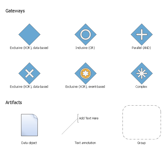
The vector stencils library "Gateways BPMN 1.2" contains symbols: data-based and event-based exclusive (XOR), inclusive (OR), parallel (AND), complex.
The vector stencils library "Artifacts BPMN 1.2" contains symbols: data object, text annotation, and group.
Use these shapes for creating the business process diagrams using the ConceptDraw PRO diagramming and vector drawing software.
"Gateway.
A gateway is represented with a diamond shape and determines forking and merging of paths, depending on the conditions expressed.
Exclusive.
Used to create alternative flows in a process because only one of the paths can be taken, it is called exclusive.
Event Based.
The condition determining the path of a process is based on an evaluated event.
Parallel.
Used to create parallel paths without evaluating any conditions.
Inclusive.
Used to create alternative flows where all paths are evaluated.
Exclusive Event Based.
An event is being evaluated to determine which of mutually exclusive paths will be taken.
Complex.
Used to model complex synchronization behavior.
Parallel Event Based.
Two parallel process are started based on an event but there is no evaluation of the event. ...
Artifacts allow developers to bring some more information into the model/ diagram. In this way the model/ diagram becomes more readable. There are three pre-defined Artifacts and they are:
(1) Data objects: Data objects show the reader which data is required or produced in an activity.
(2) Group: A Group is represented with a rounded-corner rectangle and dashed lines. The group is used to group different activities but does not affect the flow in the diagram.
(3) Annotation: An annotation is used to give the reader of the model/ diagram an understandable impression." [Business Process Model and Notation. Wikipedia]
The example "Design elements - Gateways and artifacts BPMN 1.2" is included in the Business Process Diagram solution from the Business Processes area of ConceptDraw Solution Park.
BPMN 1.2 gateway and artifact symbols
IDEF1X Standard

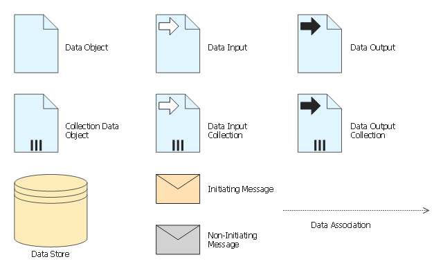
The vector stencils library "Data" contains 10 data symbols: data object, collection data object, data input and output, data input and output collections, data store, initiating and non-initiating messages, data association.
Use these shapes for drawing business process diagrams (BPMN 2.0) using the ConceptDraw PRO diagramming and vector drawing software.
"Artifacts allow developers to bring some more information into the model/ diagram. In this way the model/ diagram becomes more readable. There are three pre-defined Artifacts and they are:
(1) Data objects: Data objects show the reader which data is required or produced in an activity.
(2) Group: A Group is represented with a rounded-corner rectangle and dashed lines. The group is used to group different activities but does not affect the flow in the diagram.
(3) Annotation: An annotation is used to give the reader of the model/ diagram an understandable impression." [Business Process Model and Notation. Wikipedia]
The example "Design elements - Data BPMN 2.0" is included in the Business Process Diagram solution from the Business Processes area of ConceptDraw Solution Park.
BPMN 2.0 data symbols
- Sql Entity Relation Symbols Dash Lines
- How I Represent Dashed Line Notation In Straight Line
- Flow Chart Broken Line Meaning
- Dotted Line Process Map
- Line Diagram For Bank Building O
- Design elements - Bank UML sequence diagram | Design elements ...
- Sequence Diagram How To Draw Asynchronous
- Uml Sequence Diagram Symbols
- Dotted Line In Flowchart Meaning
- Flowchart Dashed Line
- Dotted Lines In Activity Diagram Symbols
- Organizational Chart Broken Line Symbol
- UML Sequence Diagram . Design Elements | UML Sequence ...
- Basic Flowchart Symbols and Meaning | Data Flow Diagram ...
- Sequence Diagram for Cloud Computing | UML Sequence Diagram ...
- Vector stencils library - Sequence diagram | Design elements - UML ...
- Sequence Diagram Symbols
- Design elements - Bank UML sequence diagram
- BPMN 2.0 | Design elements - Data BPMN 2.0 | Business Process ...
- UML Sequence Diagram . Design Elements | Process Flowchart ...
- ERD | Entity Relationship Diagrams, ERD Software for Mac and Win
- Flowchart | Basic Flowchart Symbols and Meaning
- Flowchart | Flowchart Design - Symbols, Shapes, Stencils and Icons
- Flowchart | Flow Chart Symbols
- Electrical | Electrical Drawing - Wiring and Circuits Schematics
- Flowchart | Common Flowchart Symbols
- Flowchart | Common Flowchart Symbols