"Component diagram shows components, provided and required interfaces, ports, and relationships between them. This type of diagrams is used in Component-Based Development (CBD) to describe systems with Service-Oriented Architecture (SOA).
Component-based development is based on assumptions that previously constructed components could be reused and that components could be replaced by some other "equivalent" or "conformant" components, if needed.
The artifacts that implement component are intended to be capable of being deployed and re-deployed independently, for instance to update an existing system.
Components in UML could represent:
(1) logical components (e.g., business components, process components), and
(2) physical components (e.g., CORBA components, EJB components, COM+ and .NET components, WSDL components, etc.),
along with the artifacts that implement them and the nodes on which they are deployed and executed. It is anticipated that profiles based around components will be developed for specific component technologies and associated hardware and software environments." [uml-diagrams.org/ component-diagrams.html]
The template "UML component diagram" for the ConceptDraw PRO diagramming and vector drawing software is included in the Rapid UML solution from the Software Development area of ConceptDraw Solution Park.
www.conceptdraw.com/ solution-park/ software-uml
UML component diagram

The vector stencils library "UML component diagrams" contains 36 symbols for the ConceptDraw PRO diagramming and vector drawing software.
"In the Unified Modeling Language, a component diagram depicts how components are wired together to form larger components and or software systems. They are used to illustrate the structure of arbitrarily complex systems. ...
Symbols.
This may have a visual stereotype in the top right of the rectangle of a small rectangle with two even smaller rectangles jutting out on the left.
The lollipop, a small circle on a stick represents an implemented or provided interface. The socket symbol is a semicircle on a stick that can fit around the lollipop. This socket is a dependency or needed interface." [Component diagram. Wikipedia]
The example "Design elements - UML component diagrams" is included in the Rapid UML solution from the Software Development area of ConceptDraw Solution Park.
UML component diagram symbols

"Component diagram shows components, provided and required interfaces, ports, and relationships between them. This type of diagrams is used in Component-Based Development (CBD) to describe systems with Service-Oriented Architecture (SOA).
Component-based development is based on assumptions that previously constructed components could be reused and that components could be replaced by some other "equivalent" or "conformant" components, if needed.
The artifacts that implement component are intended to be capable of being deployed and re-deployed independently, for instance to update an existing system.
Components in UML could represent:
(1) logical components (e.g., business components, process components), and
(2) physical components (e.g., CORBA components, EJB components, COM+ and .NET components, WSDL components, etc.),
along with the artifacts that implement them and the nodes on which they are deployed and executed. It is anticipated that profiles based around components will be developed for specific component technologies and associated hardware and software environments." [uml-diagrams.org/ component-diagrams.html]
The template "UML component diagram" for the ConceptDraw PRO diagramming and vector drawing software is included in the Rapid UML solution from the Software Development area of ConceptDraw Solution Park.
www.conceptdraw.com/ solution-park/ software-uml
Component-based development is based on assumptions that previously constructed components could be reused and that components could be replaced by some other "equivalent" or "conformant" components, if needed.
The artifacts that implement component are intended to be capable of being deployed and re-deployed independently, for instance to update an existing system.
Components in UML could represent:
(1) logical components (e.g., business components, process components), and
(2) physical components (e.g., CORBA components, EJB components, COM+ and .NET components, WSDL components, etc.),
along with the artifacts that implement them and the nodes on which they are deployed and executed. It is anticipated that profiles based around components will be developed for specific component technologies and associated hardware and software environments." [uml-diagrams.org/ component-diagrams.html]
The template "UML component diagram" for the ConceptDraw PRO diagramming and vector drawing software is included in the Rapid UML solution from the Software Development area of ConceptDraw Solution Park.
www.conceptdraw.com/ solution-park/ software-uml
UML component diagram
 Website Wireframe
The innovative Website Wireframe solution enhances the ConceptDraw PRO v10 functionality with newest wireframe tools, libraries with variety of predesigned icons, symbols, buttons, graphics, forms, boxes, and many other vector elements, templates and professionally designed samples, which make it the best wireframing software. Website Wireframe solution gives you significant advantages when designing and maintaining websites, creating skeletal and content-free depictions of website structure, making website prototypes and planning the content arrangement before committing to design, also speeds up the processes of sketching, producing and sharing wireframe examples of website style and interface design.
HelpDesk
How to Make a Web Page from Your Metro Map

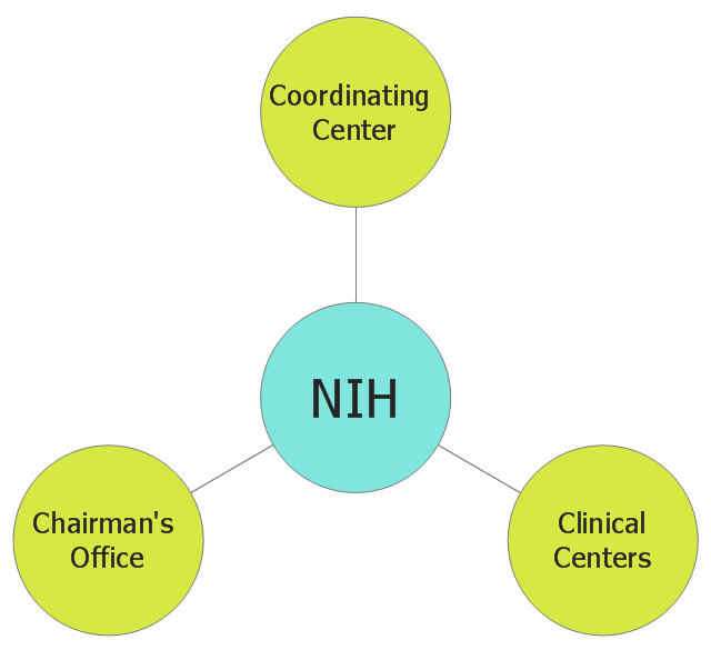
This circle-spoke diagram sample shows the National Institutes of Health (NIH) components. It was designed on the base of the circle-spoke diagram from the webpage "Type 1 Diabetes TrialNet: Clinical Centers" from the website of the U.S. National Institutes of Health (NIH).
[grants.nih.gov/ grants/ guide/ rfa-files/ RFA-DK-08-011.html]
"The National Institutes of Health (NIH) is a biomedical research facility primarily located in Bethesda, Maryland. An agency of the United States Department of Health and Human Services, it is the primary agency of the United States government responsible for biomedical and health-related research. The NIH both conducts its own scientific research through its Intramural Research Program (IRP) and provides major biomedical research funding to non-NIH research facilities through its Extramural Research Program. ...
The NIH comprises 27 separate institutes and centers that conduct research in different disciplines of biomedical science." [National Institutes of Health. Wikipedia]
The diagram example "NIH components" was created using the ConceptDraw PRO diagramming and vector drawing software extended with the Basic Circle-Spoke Diagrams solution from the area "What is a Diagram" of ConceptDraw Solution Park.
Circle-spoke diagram
HelpDesk
How to Make a Web Page from Infographics

HelpDesk
How to Save a Diagram as a Web Page in ConceptDraw PRO

tags that are needed to display your diagrams in a Web browser, so all you have to do is design their
appearance.
- Web Page Component
- Webpage Components With Diagram
- UML component diagram - Template
- UML Component Diagram
- UML component diagram
- UML component diagram - Template | Design elements ...
- UML Deployment Diagram Example
- UML component diagram - Template | UML deployment diagram ...
- The Block Diagram On How To Make A Web Page
- Design elements - UML component diagrams
- UML Tool & UML Diagram Examples | UML Component Diagram ...
- UML Component Diagram . Design Elements
- Website Design Flowchart Example
- Example Block Diagram For Website Design
- Block Diagram Symbols Server Webpage Database
- Cloud Computing Architecture Diagrams | Network Components ...
- Website launch - Flowchart | UML Diagram | Cisco LAN. Cisco icons ...
- UML Component Diagram
- Website launch - Flowchart | Cisco LAN - Vector stencils library ...
- Data flow Model Diagram
- ERD | Entity Relationship Diagrams, ERD Software for Mac and Win
- Flowchart | Basic Flowchart Symbols and Meaning
- Flowchart | Flowchart Design - Symbols, Shapes, Stencils and Icons
- Flowchart | Flow Chart Symbols
- Electrical | Electrical Drawing - Wiring and Circuits Schematics
- Flowchart | Common Flowchart Symbols
- Flowchart | Common Flowchart Symbols