This cafe electrical floor plan sample shows the outlet and switch layout.
"An electrical drawing, is a type of technical drawing that shows information about power, lighting, and communication for an engineering or architectural project. Any electrical working drawing consists of "lines, symbols, dimensions, and notations to accurately convey an engineering's design to the workers, who install the electrical system on the job".
A complete set of working drawings for the average electrical system in large projects usually consists of:
(1) A plot plan showing the building's location and outside electrical wiring.
(2) Floor plans showing the location of electrical systems on every floor.
(3) Power-riser diagrams showing panel boards.
(4) Control wiring diagrams.
(5) Schedules and other information in combination with construction drawings.
Electrical drafters prepare wiring and layout diagrams used by workers who erect, install, and repair electrical equipment and wiring in communication centers, power plants, electrical distribution systems, and buildings." [Electrical drawing. Wikipedia]
The outlet and switch layout example "Cafe electrical floor plan" was created using the ConceptDraw PRO diagramming and vector drawing software extended with the Electric and Telecom Plans solution from the Building Plans area of ConceptDraw Solution Park.
Outlet and switch layout

This electrical floot plan sample shows the Power socket outlet layout.
"The term plug is in general and technical use in all forms of English, common alternatives being power plug, electric plug, and (in the UK) plug top. The normal technical term (in both British and International English) for an AC power socket is socket-outlet, but in non-technical common use a number of other terms are used. In British English the general term is socket, but there are numerous common alternatives, including power point, plug socket, wall socket, and wall plug. In American English receptacle and outlet are common, sometimes with qualifiers such as wall outlet, electrical outlet and electrical receptacle, all of these sometimes to be found in the same document. A socket may be surrounded by a decorative and/ or protective cover called a wall plate, face plate, outlet cover, socket cover, or wall cover. In some designs this is an integral piece with the socket itself, bought and installed as a single unit." [AC power plugs and sockets. Wikipedia]
The electrical floot plan example "Power socket outlet layout" was created using the ConceptDraw PRO diagramming and vector drawing software extended with the Electric and Telecom Plans solution from the Building plans area of ConceptDraw Solution Park.
Electrical floot plan

 Electric and Telecom Plans
This solution extends ConceptDraw PRO software with samples, templates and libraries of vector stencils for drawing the Electric and Telecom Plans.
This electrical floor plan sample shows the lighting and switch layout.
"In building wiring, a light switch is a switch, most commonly used to operate electric lights, permanently connected equipment, or electrical outlets. Portable lamps such as table lamps will have a light switch mounted on the socket, base, or in-line with the cord. Manually operated on/ off switches may be substituted by remote control switches, or light dimmers that allow controlling the brightness of lamps as well as turning them on or off. Light switches are also found in flashlights and automobiles and other vehicles." [Light switch. Wikipedia]
The electrical floor plan example "Lighting and switch layout" was created using the ConceptDraw PRO diagramming and vector drawing software extended with the Electric and Telecom Plans solution from the Building plans area of ConceptDraw Solution Park.
Electrical floor plan

"The Ethernet physical layer is the physical layer component of the Ethernet family of computer network standards.
The Ethernet physical layer evolved over a considerable time span and encompasses quite a few physical media interfaces and several magnitudes of speed. The speed ranges from 1 Mbit/ s to 100 Gbit/ s, while the physical medium can range from bulky coaxial cable to twisted pair and optical fiber. In general, network protocol stack software will work similarly on all physical layers.
10-gigabit Ethernet was already used in both enterprise and carrier networks by 2007, with 40 Gbit/ s and 100 Gbit/ s Ethernet ratified. ...
Many Ethernet adapters and switch ports support multiple speeds, using autonegotiation to set the speed and duplex for the best values supported by both connected devices. If auto-negotiation fails, a multiple-speed device will sense the speed used by its partner, but will assume half-duplex. A 10/ 100 Ethernet port supports 10BASE-T and 100BASE-TX. A 10/ 100/ 1000 Ethernet port supports 10BASE-T, 100BASE-TX, and 1000BASE-T." [Ethernet physical layer. Wikipedia]
The LAN equipment and cabling layout floorplan example "Ethernet local area network layout floor plan" was created using the ConceptDraw PRO diagramming and vector drawing software extended with the Network Layout Floor Plans solution from the Computer and Networks area of ConceptDraw Solution Park.
Ethernet LAN layout floorplan

The vector stencils library "Network layout floorplan" contain 34 symbol icons for drawing computer network floor plans and communication equipment and cabling layouts.
"Networking hardware may also be known as network equipment or computer networking devices. Units which are the last receiver or generate data are called hosts or data terminal equipment.
All these terms refer to devices facilitating the use of a computer network. Specifically, they mediate data in a computer network. ...
Typically, networking hardware includes gateways, routers, network bridges, switches, hubs, and repeaters. But it also includes hybrid network devices such as multilayer switches, protocol converters, bridge routers, proxy servers, firewalls, network address translators, multiplexers, network interface controllers, wireless network interface controllers, modems, ISDN terminal adapters, line drivers, wireless access points, networking cables and other related hardware.
The most common kind of networking hardware today is a copper-based Ethernet adapter because of its standard inclusion on most modern computer systems. Wireless networking has, however, become increasingly popular, especially for portable and handheld devices.
Other hardware prevalent in computer networking includes data center equipment (such as file servers, database servers and storage areas), network services (such as DNS, DHCP, email, etc.) as well as devices which assure content delivery." [Networking hardware. Wikipedia]
The shapes example "Design elements - Network layout floorplan" was created using the ConceptDraw PRO diagramming and vector drawing software extended with the Network Layout Floor Plans solution from the Computer and Networks area of ConceptDraw Solution Park.
Network layout floor plan symbols

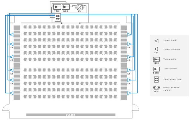
This electrical drawing sample shows video and audio equipment layout on the cinema seating plan.
"Digital cinema refers to the use of digital technology to distribute or project motion pictures as opposed to the historical use of motion picture film. A movie can be distributed via hard drives, the Internet, dedicated satellite links or optical disks such as DVDs and Blu-ray Discs. Digital movies are projected using a digital projector instead of a conventional film projector. Digital cinema is distinct from high-definition television and is not dependent on using television or high-definition video standards, aspect ratios, or frame rates. In digital cinema, resolutions are represented by the horizontal pixel count, usually 2K (2048×1080 or 2.2 megapixels) or 4K (4096×2160 or 8.8 megapixels)." [Digital cinema. Wikipedia]
The electrical floor plan example "Cinema video and audio equipment layout" was created using the ConceptDraw PRO diagramming and vector drawing software extended with the Electric and Telecom Plans solution from the Building plans area of ConceptDraw Solution Park.
Electrical floor plan
"A computer network or data network is a telecommunications network that allows computers to exchange data. In computer networks, networked computing devices pass data to each other along data connections. The connections (network links) between nodes are established using either cable media or wireless media. ...
Network computer devices that originate, route and terminate the data are called network nodes. Nodes can include hosts such as personal computers, phones, servers as well as networking hardware. Two such devices are said to be networked together when one device is able to exchange information with the other device, whether or not they have a direct connection to each other. ...
Users and network administrators typically have different views of their networks. Users can share printers and some servers from a workgroup, which usually means they are in the same geographic location and are on the same LAN, whereas a Network Administrator is responsible to keep that network up and running. A community of interest has less of a connection of being in a local area, and should be thought of as a set of arbitrarily located users who share a set of servers, and possibly also communicate via peer-to-peer technologies.
Network administrators can see networks from both physical and logical perspectives. The physical perspective involves geographic locations, physical cabling, and the network elements (e.g., routers, bridges and application layer gateways) that interconnect the physical media. Logical networks, called, in the TCP/ IP architecture, subnets, map onto one or more physical media. For example, a common practice in a campus of buildings is to make a set of LAN cables in each building appear to be a common subnet, using virtual LAN (VLAN) technology." [Computer network. Wikipedia]
The network layout floorplan template for the ConceptDraw PRO diagramming and vector drawing software is included in the Network Layout Floor Plans solution from the Computer and Networks area of ConceptDraw Solution Park.
Network layout floor plan template

"The Ethernet physical layer is the physical layer component of the Ethernet family of computer network standards.
The Ethernet physical layer evolved over a considerable time span and encompasses quite a few physical media interfaces and several magnitudes of speed. The speed ranges from 1 Mbit/ s to 100 Gbit/ s, while the physical medium can range from bulky coaxial cable to twisted pair and optical fiber. In general, network protocol stack software will work similarly on all physical layers.
10-gigabit Ethernet was already used in both enterprise and carrier networks by 2007, with 40 Gbit/ s and 100 Gbit/ s Ethernet ratified. ...
Many Ethernet adapters and switch ports support multiple speeds, using autonegotiation to set the speed and duplex for the best values supported by both connected devices. If auto-negotiation fails, a multiple-speed device will sense the speed used by its partner, but will assume half-duplex. A 10/ 100 Ethernet port supports 10BASE-T and 100BASE-TX. A 10/ 100/ 1000 Ethernet port supports 10BASE-T, 100BASE-TX, and 1000BASE-T." [Ethernet physical layer. Wikipedia]
The LAN equipment and cabling layout floorplan example "Ethernet local area network layout floor plan" was created using the ConceptDraw PRO diagramming and vector drawing software extended with the Network Layout Floor Plans solution from the Computer and Networks area of ConceptDraw Solution Park.
The Ethernet physical layer evolved over a considerable time span and encompasses quite a few physical media interfaces and several magnitudes of speed. The speed ranges from 1 Mbit/ s to 100 Gbit/ s, while the physical medium can range from bulky coaxial cable to twisted pair and optical fiber. In general, network protocol stack software will work similarly on all physical layers.
10-gigabit Ethernet was already used in both enterprise and carrier networks by 2007, with 40 Gbit/ s and 100 Gbit/ s Ethernet ratified. ...
Many Ethernet adapters and switch ports support multiple speeds, using autonegotiation to set the speed and duplex for the best values supported by both connected devices. If auto-negotiation fails, a multiple-speed device will sense the speed used by its partner, but will assume half-duplex. A 10/ 100 Ethernet port supports 10BASE-T and 100BASE-TX. A 10/ 100/ 1000 Ethernet port supports 10BASE-T, 100BASE-TX, and 1000BASE-T." [Ethernet physical layer. Wikipedia]
The LAN equipment and cabling layout floorplan example "Ethernet local area network layout floor plan" was created using the ConceptDraw PRO diagramming and vector drawing software extended with the Network Layout Floor Plans solution from the Computer and Networks area of ConceptDraw Solution Park.
Ethernet LAN layout floorplan
- Lighting and switch layout | How To use House Electrical Plan ...
- Power socket outlet layout | How To use House Electrical Plan ...
- How To use House Electrical Plan Software | Plant Layout Plans ...
- How To use House Electrical Plan Software | Power socket outlet ...
- Cafe electrical floor plan | Restaurant Floor Plans Samples ...
- Electrical Convenience Layout
- How To use House Electrical Plan Software | Residential Electric ...
- How To use House Electrical Plan Software | Cafe electrical floor ...
- How To use House Electrical Plan Software | Electrical Drawing ...
- How To use House Electrical Plan Software | Electrical and Telecom ...
- Network Layout Floor Plans | Ethernet cable layout | Home ...
- Interior Design Office Layout Plan Design Element | How To use ...
- Reflected ceiling plan | Classroom lighting - Reflected ceiling plan ...
- How To use House Electrical Plan Software | Home Electrical Plan ...
- How To use House Electrical Plan Software | Electrical Symbols ...
- How To use House Electrical Plan Software | Lighting and switch ...
- Cafe electrical floor plan | Design elements - Qualifying | Electrical ...
- Electrical and Telecom Plan Software
- Power socket outlet layout | Electrical Symbols, Electrical Diagram ...
- How To use House Electrical Plan Software | Design elements ...
- ERD | Entity Relationship Diagrams, ERD Software for Mac and Win
- Flowchart | Basic Flowchart Symbols and Meaning
- Flowchart | Flowchart Design - Symbols, Shapes, Stencils and Icons
- Flowchart | Flow Chart Symbols
- Electrical | Electrical Drawing - Wiring and Circuits Schematics
- Flowchart | Common Flowchart Symbols
- Flowchart | Common Flowchart Symbols