UML Diagram Visio

Using the 13 libraries of the Rapid UML Solution for ConceptDraw DIAGRAM you can create your own visual vector UML diagrams quick and easy.
UML Deployment Diagram. Diagramming Software for Design UML Diagrams


UML Deployment Diagram Example - ATM System UML diagrams

This sample shows the work of the ATM (Automated Teller Machine) banking system that is used for service and performing of the banking transactions using ATMs. System engineers can use comprehensive UML diagrams solution.
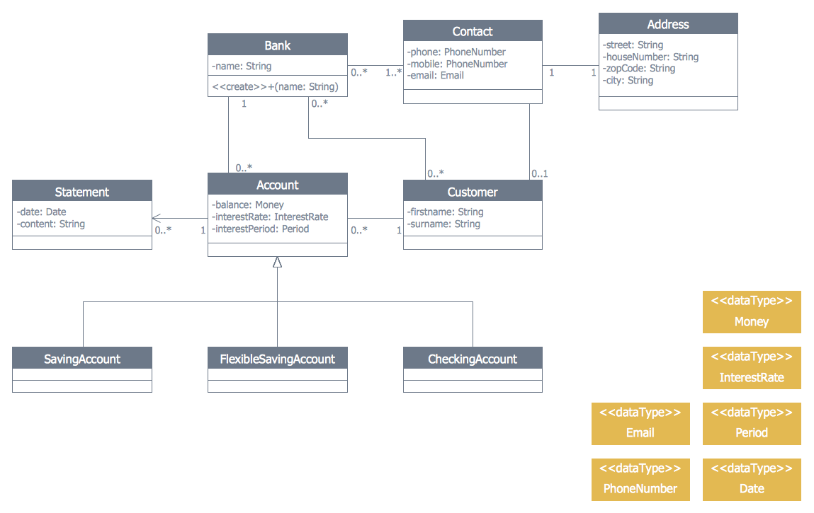
Bank UML Diagram

UML Deployment Diagram
Use ConceptDraw DIAGRAM with UML deployment diagram templates, samples and stencil library from Rapid UML solution to model the physical deployment of artifacts on nodes of your software system.
UML Tool & UML Diagram Examples

Solution RapidUML from Software Development area of ConceptDraw Solution Park provides templates, examples and 13 vector stencils libraries for drawing all types of UML 1.x and 2.x diagrams using ConceptDraw DIAGRAM diagramming and vector drawing software.
Use these UML diagram templates and examples to quickly start drawing your own UML diagrams.
UML Deployment Diagram. Design Elements

ConceptDraw has 393 vector stencils in the 13 libraries that helps you to start using software for designing your own UML Diagrams. You can use the appropriate stencils of UML notation from UML Deployment library.
UML Notation

Two types of diagrams are used in UML: Structure Diagrams and Behavior Diagrams. Behavior Diagrams represent the processes proceeding in a modeled environment. Structure Diagrams represent the elements that compose the system.
Banking System
Diagramming Software for UML Composite Structure Diagrams

- UML Diagram Visio | UML Deployment Diagram . Diagramming ...
- UML Deployment Diagram . Diagramming Software for Design UML ...
- Rapid UML | Rapid UML | Visio Uml Physical Deployment Model
- UML Component Diagram | Process Flowchart | UML Deployment ...
- Visio Uml Deployment Diagram
- How To Create Class Diagram In Visio
- Deployment Diagram In Uml With Example
- UML Deployment Diagram . Diagramming Software for Design UML ...
- Visio Files and ConceptDraw | DroidDia prime | Format Uml ...
- UML Activity Diagram | UML Deployment Diagram Example - ATM ...
- ERD | Entity Relationship Diagrams, ERD Software for Mac and Win
- Flowchart | Basic Flowchart Symbols and Meaning
- Flowchart | Flowchart Design - Symbols, Shapes, Stencils and Icons
- Flowchart | Flow Chart Symbols
- Electrical | Electrical Drawing - Wiring and Circuits Schematics
- Flowchart | Common Flowchart Symbols
- Flowchart | Common Flowchart Symbols