 Audio and Video Connectors
Audio and video connectors solution extends ConceptDraw PRO software with templates, samples and library of vector stencils for drawing audio and video hook up diagrams.
HelpDesk
How to Create a Hook Up Diagram

 Audio and Video Connectors
The Audio and Video Connectors solution contains a set of video connectors, audio connectors and s video connection; you will also find pre-designed objects, libraries, templates, and samples, allowing quick and easy diagramming of various configurations
 Entity-Relationship Diagram (ERD)
Entity-Relationship Diagram (ERD) solution extends ConceptDraw PRO software with templates, samples and libraries of vector stencils from drawing the ER-diagrams by Chen's and crow’s foot notations.
 ConceptDraw Solution Park
ConceptDraw Solution Park collects graphic extensions, examples and learning materials
 Audio, Video, Media
Use it to make professional-looking documents, impressive presentations, and efficient websites with colorful and vivid illustrations and schematics of digital audio, video and photo gadgets and devices, audio video connections and configurations, S Video connection, HD and 3D television systems, home entertainment systems, Closed-circuit television (CCTV) surveillance systems. All audio video schematics, drawings and illustrations designed in ConceptDraw PRO are professional looking, clear and understandable for all thanks to applying the most commonly used standards of designations, and are effective for demonstrating in front of a small audience and on the big screens.
HelpDesk
How to Create a Data Flow Diagram using ConceptDraw PRO
 example")
HelpDesk
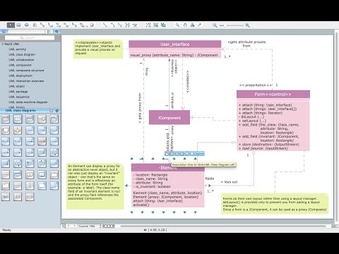
How to Create a UML Diagram Using ConceptDraw PRO

HelpDesk
How to Make a UML Diagram in ConceptDraw PRO

Using UML during the modeling process has a number of benefits — for one, the entire development team can share information and collaborate using common language, diagrams and software, something that's not possible when using a more task-specific programming language.
It allows team members to create system 'blueprin
HelpDesk
How to Create a CCTV Diagram in ConceptDraw PRO

CCTV diagram should include the scheme of strategic placement of video cameras, which capture and transmit videos to either a private network of monitors for real-time viewing, or to a video recorder for later reference. CCTV is commonly used for surveillance and security purposes. Using ConceptDraw PRO with the Security and Access Plans Solution lets you create professional looking video surveillance CCTV system plans, security plans, and access schemes.
- Network Diagram Examples | Audio and Video Connectors ...
- Entity-Relationship Diagram (ERD) | Audio, Video , Media | Artwork ...
- Basic CCTV System Diagram . CCTV Network Diagram Example ...
- Fishbone Diagram | Audio, Video , Media | Fishbone Examples In ...
- Home area network (HAN) wiring diagram | Design elements - Video ...
- Audio and Video Connectors | Entity-Relationship Diagram (ERD ...
- Audio and Video Connectors | Fishbone Diagram | Event-driven ...
- Event-driven Process Chain Diagrams EPC | Audio and Video ...
- Audio and Video Connectors | UML Diagrams with ConceptDraw ...
- Audio and Video Connectors | Illustration | Entity-Relationship ...
- Entity-Relationship Diagram (ERD) | Audio and Video Connectors ...
- CCTV Network Diagram Software | Audio, Video , Media | Illustration ...
- Fishbone Diagram | Event-driven Process Chain Diagrams EPC ...
- Audio video hook up diagram template | Audio and Video ...
- Fishbone Diagram | Design elements - Fishbone diagram | Audio ...
- Audio and Video Connectors | CCTV Network Diagram Software ...
- How to Create a CCTV Schematic Diagram Using Custom Library ...
- Audio and Video Connectors | How To Create CCTV Network ...
- UML Use Case Diagrams | UML Tool & UML Diagram Examples ...
- Entity-Relationship Diagram (ERD) | Audio, Video , Media | Business ...
- ERD | Entity Relationship Diagrams, ERD Software for Mac and Win
- Flowchart | Basic Flowchart Symbols and Meaning
- Flowchart | Flowchart Design - Symbols, Shapes, Stencils and Icons
- Flowchart | Flow Chart Symbols
- Electrical | Electrical Drawing - Wiring and Circuits Schematics
- Flowchart | Common Flowchart Symbols
- Flowchart | Common Flowchart Symbols