Process Flow Chart

ConceptDraw DIAGRAM diagramming and vector drawing software extended with Flowcharts Solution from the "Diagrams" Area of ConceptDraw Solution Park is the best way to create Process Flow Chart and other types of flowcharts.
Mechanical Drawing Software

 Mechanical Engineering
This solution extends ConceptDraw DIAGRAM.9 mechanical drawing software (or later) with samples of mechanical drawing symbols, templates and libraries of design elements, for help when drafting mechanical engineering drawings, or parts, assembly, pneumatic,
Piping and Instrumentation Diagram Software

Plumbing and Piping Plans solution helps you create quick and easy: key piping and instrument details ,piping diagrams, instrumentation diagrams, schemes of hot and cold water supply systems, control and shutdown schemes, diagrams of plumbing systems, heating schemes, schematics of waste water disposal systems, safety and regulatory requirements, diagrams of ventilation systems, mechanical diagrams, industrial diagrams, basic start up and operational information.
"A process flow diagram (PFD) is a diagram commonly used in chemical and process engineering to indicate the general flow of plant processes and equipment. The PFD displays the relationship between major equipment of a plant facility and does not show minor details such as piping details and designations. Another commonly used term for a PFD is a flowsheet. ...
Process flow diagrams of multiple process units within a large industrial plant will usually contain less detail and may be called block flow diagrams or schematic flow diagrams." [Process flow diagram. Wikipedia]
The process flow diagram (PFD) template for the ConceptDraw PRO diagramming and vector drawing software is included in the Chemical and Process Engineering solution from the Engineering area of ConceptDraw Solution Park.
Process flow diagram (PFD) template
-template-process-flow-diagram-(pfd)-template.png--diagram-flowchart-example.png)
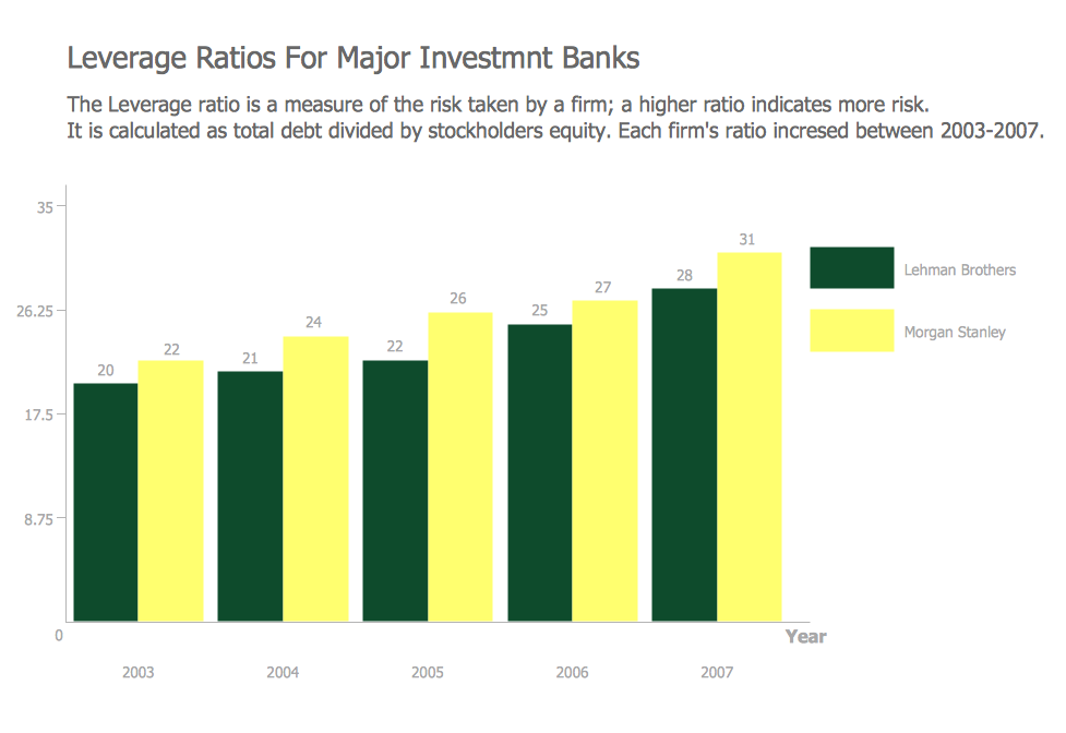
Sales Growth. Bar Graphs Example

Financial Comparison Chart
Building Drawing Software for Design Seating Plan


 Chemical and Process Engineering
This chemical engineering solution extends ConceptDraw DIAGRAM.9.5 (or later) with process flow diagram symbols, samples, process diagrams templates and libraries of design elements for creating process and instrumentation diagrams, block flow diagrams (BFD
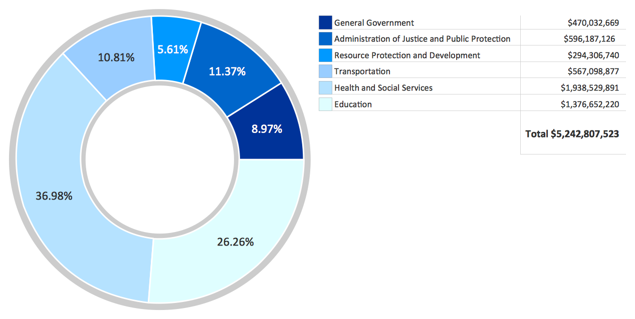
How to Create a Pie Chart
- Valve Chart Template
- Hydraulic 4-ported 3-position valve template - Win | Mechanical ...
- Mechanical Engineering | Pneumatic 5-ported 3-position valve ...
- Pneumatic 5-ported 3-position valve template - Mac | Mechanical ...
- Valve Symbol Chart
- Pneumatic 5-ported 3-position valve template - Mac | Mechanical ...
- Valve Manufacturing Process Flow Chart
- Process Flow Chart | Mechanical Engineering | Chemical and ...
- Pneumatic 5-ported 3-position valve template - Mac | Design ...
- Pneumatic 5-ported 3-position valve template - Mac | Design ...
- ERD | Entity Relationship Diagrams, ERD Software for Mac and Win
- Flowchart | Basic Flowchart Symbols and Meaning
- Flowchart | Flowchart Design - Symbols, Shapes, Stencils and Icons
- Flowchart | Flow Chart Symbols
- Electrical | Electrical Drawing - Wiring and Circuits Schematics
- Flowchart | Common Flowchart Symbols
- Flowchart | Common Flowchart Symbols