UML Flowchart Symbols

The Rapid UML solution for ConceptDraw DIAGRAM software offers diversity of UML flowchart symbols for drawing all types of UML diagrams.
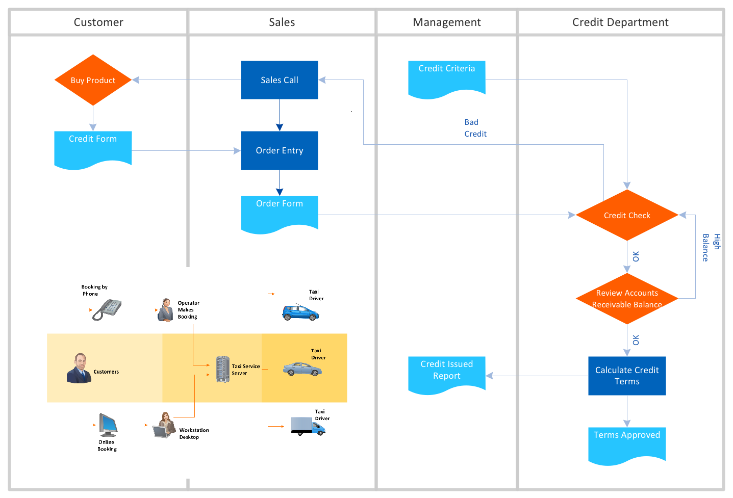
Cross-Functional Flowchart (Swim Lanes)

Use flowchart maker of ConceptDraw DIAGRAM enhanced with solutions from ConceptDraw Solution Park to create diagrams to present and explain structures, process flows, logical relationships, networks, design schemes and other visually organized information and knowledge.
Basic Diagramming

Use Basic Diagramming solution to draw you own diagrams, charts and graphs for graphic communication, explanation of business and personal ideas and concepts, simple visual presentation of numerical data, complex structures, logical relations, step-by-step flows of actions or operations.

Flowchart Maker
Business graphic applications show a special knowledge representations and include many features for creating schematic pictures. These graphic tools are known as flowchart maker or flowchart maker software.
UML Diagram Types List

ConceptDraw Arrows10 Technology

You don't know how should diagramming software work?
Is it possible to develop a diagram as quickly as the ideas come to you?
Yes. The innovative ConceptDraw Arrows10 Technology - This is more than enough versatility to draw any type of diagram with any degree of complexity.
You can start draw your diagram manually now.
UML Class Diagram Generalization Example UML Diagrams

This sample describes the use of the classes, the generalization associations between them, the multiplicity of associations and constraints. Provided UML diagram is one of the examples set that are part of Rapid UML solution.
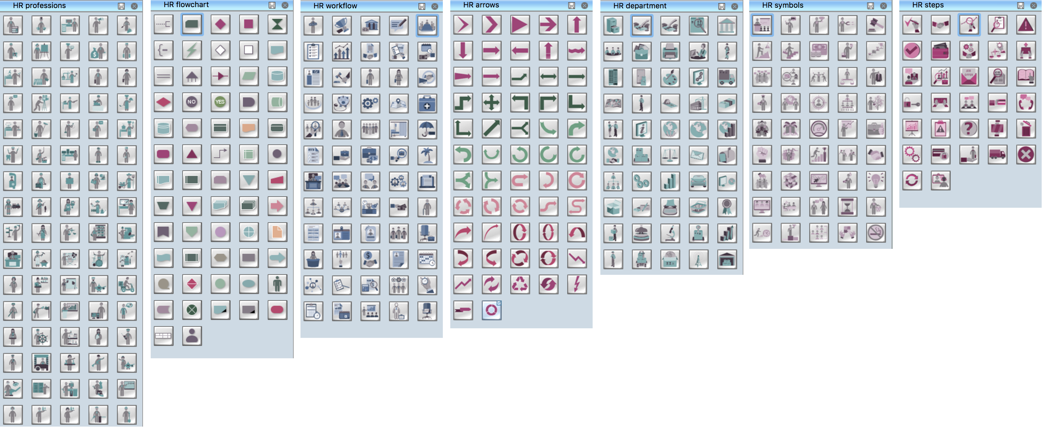
HR Flowchart Symbols
UML Use Case Diagrams


ConceptDraw Arrows10 Technology
Using any other connection point provides a static connection, when you move connected objects the connector stays attached to the same point.
- User Behavior Flow Chart
- Block Diagrams | HR Flowcharts | Basic Circle-Spoke Diagrams ...
- Store reporting flowchart | How to Create a Bank ATM Use Case ...
- Importance Of Organizational Behavior Flow Chart Diagram
- Organizational Behavior Flow Chart
- Basic Flowchart Symbols and Meaning | Cross Functional Flowchart ...
- Process Flowchart | Basic Flowchart Symbols and Meaning | Basic ...
- Flow Charts For Organizational Behaviour
- Block diagram - Types of individual behavior in organization ...
- Organizational culture - Triangle diagram | Block diagram - Types of ...
- ERD | Entity Relationship Diagrams, ERD Software for Mac and Win
- Flowchart | Basic Flowchart Symbols and Meaning
- Flowchart | Flowchart Design - Symbols, Shapes, Stencils and Icons
- Flowchart | Flow Chart Symbols
- Electrical | Electrical Drawing - Wiring and Circuits Schematics
- Flowchart | Common Flowchart Symbols
- Flowchart | Common Flowchart Symbols