Diagramming Software for Design UML Use Case Diagrams


HelpDesk
How to Create a Bank ATM Use Case Diagram

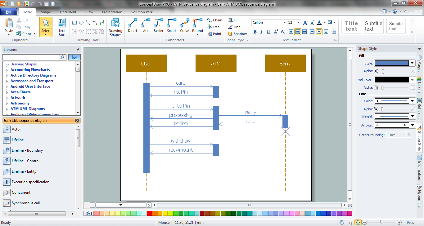
ConceptDraw DIAGRAM diagramming software, enhanced and expanded with the ATM UML Diagrams solution, offers the full range of icons, templates and design elements needed to faithfully represent ATM and banking information system architecture using UML standards. The ATM UML Diagrams solution is useful for beginner and advanced users alike. More experienced users will appreciate a full range of vector stencil libraries and ConceptDraw DIAGRAM's powerful software, that allows you to create your ATM UML diagram in a matter of moments.
Use Case Diagrams technology with ConceptDraw DIAGRAM

Diagramming Software for Design UML Activity Diagrams

Bank Sequence Diagram
UML Software

The Rapid UML Solution for ConceptDraw DIAGRAM presentsthe intuitive RapidDraw interface that helps you to make the UML Diagram of any of these 13 types quick and easy.
SSADM Diagram

The example below illustrates the waterfall model used in SSADM. This model involves 5 stages of developing a product such as requirements specification and its' analysis, design, coding and testing.
ConceptDraw DIAGRAM DFD Software

How To Create a Workflow Diagram
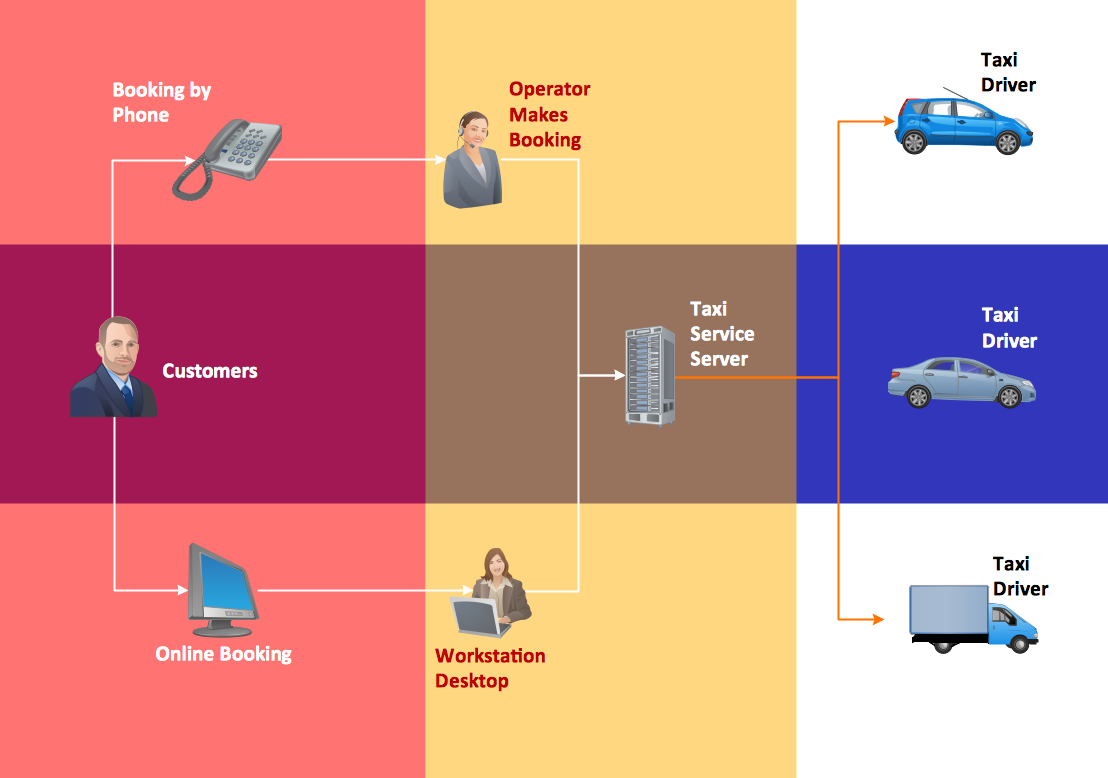
The fastest way to create a workflow diagram is using pre-designed workflow template. ConceptDraw DIAGRAM with the Workflow Diagrams solution delivers rich set of workflow diagram templates you may start from.
UML Tool & UML Diagram Examples

Solution RapidUML from Software Development area of ConceptDraw Solution Park provides templates, examples and 13 vector stencils libraries for drawing all types of UML 1.x and 2.x diagrams using ConceptDraw DIAGRAM diagramming and vector drawing software.
Use these UML diagram templates and examples to quickly start drawing your own UML diagrams.
- Uml Diagram Of Export Management System
- Activity Diagram For Import Export Management System
- Activity Diagram On Export System
- Class Diagram Of Export Mangment System
- UML Use Case Diagram Example Social Networking Sites Project ...
- Export System Use Case Diag
- Import And Export Management System Er Diagram
- How to Create a Bank ATM Use Case Diagram | Export System ...
- Usecase Diagram Of Export Management Systems
- Activity Diagram For Import Export Management System Vehicle Driver
- ERD | Entity Relationship Diagrams, ERD Software for Mac and Win
- Flowchart | Basic Flowchart Symbols and Meaning
- Flowchart | Flowchart Design - Symbols, Shapes, Stencils and Icons
- Flowchart | Flow Chart Symbols
- Electrical | Electrical Drawing - Wiring and Circuits Schematics
- Flowchart | Common Flowchart Symbols
- Flowchart | Common Flowchart Symbols