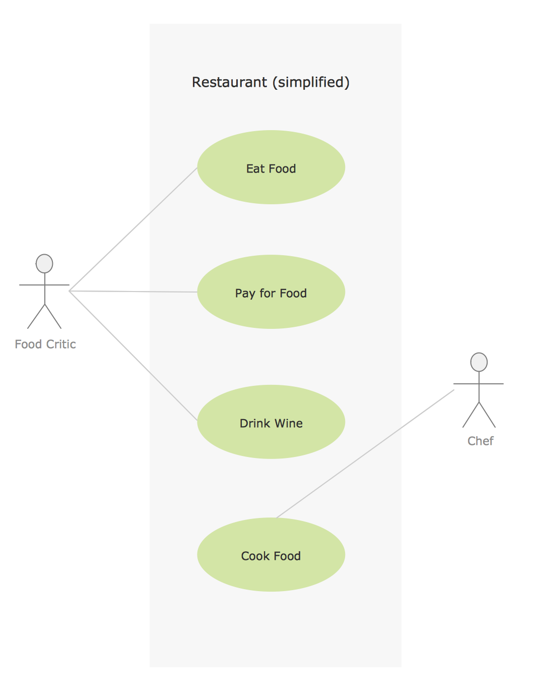
Jacobson Use Cases Diagram

Use Case Diagrams technology with ConceptDraw DIAGRAM

Model Based Systems Engineering

Sample for UML
 Data Flow Diagrams (DFD)
Data Flow Diagrams solution extends ConceptDraw DIAGRAM software with templates, samples and libraries of vector stencils for drawing the data flow diagrams (DFD).
UML Use Case Diagram Example. Registration System

This sample was created in ConceptDraw DIAGRAM diagramming and vector drawing software using the UML Use Case Diagram library of the Rapid UML Solution from the Software Development area of ConceptDraw Solution Park.
This sample shows the types of user’s interactions with the system and is used at the registration and working with the database system.
Example of DFD for Online Store (Data Flow Diagram)

Example of DFD for Online Store shows the Data Flow Diagram for online store and interactions between the Visitors, Customers and Sellers, as well as Website Information and User databases.

HelpDesk
How to Create a Data Flow Diagram

How to Build Cloud Computing Diagram Principal Cloud Manufacturing

For documenting the Cloud Computing Architecture with a goal to facilitate the communication between stakeholders are successfully used the Cloud Computing Architecture diagrams. It is convenient and easy to draw various Cloud Computing Architecture diagrams in ConceptDraw DIAGRAM software with help of tools of the Cloud Computing Diagrams Solution from the Computer and Networks Area of ConceptDraw Solution Park.
UML Class Diagram Example for GoodsTransportation System
This sample shows the concept of working of the transport company and is used by transport companies, carriers at the transportation of various goods.
 Event-driven Process Chain Diagrams
Event-Driven Process Chain Diagrams solution extends ConceptDraw DIAGRAM functionality with event driven process chain templates, samples of EPC engineering and modeling the business processes, and a vector shape library for drawing the EPC diagrams and EPC flowcharts of any complexity. It is one of EPC IT solutions that assist the marketing experts, business specialists, engineers, educators and researchers in resources planning and improving the business processes using the EPC flowchart or EPC diagram. Use the EPC solutions tools to construct the chain of events and functions, to illustrate the structure of a business process control flow, to describe people and tasks for execution the business processes, to identify the inefficient businesses processes and measures required to make them efficient.
Software Diagram Examples and Templates

Software Development area of ConceptDraw Solution Park provides 5 solutions:
Data Flow Diagrams, Entity-Relationship Diagram (ERD), Graphic User Interface, IDEFO Diagrams, Rapid UML.
SysML

ConceptDraw DIAGRAM diagramming and vector drawing software was extended with SysML Solution from the Software Development Area of ConceptDraw Solution Park specially to help systems engineers design various model systems with SysML.
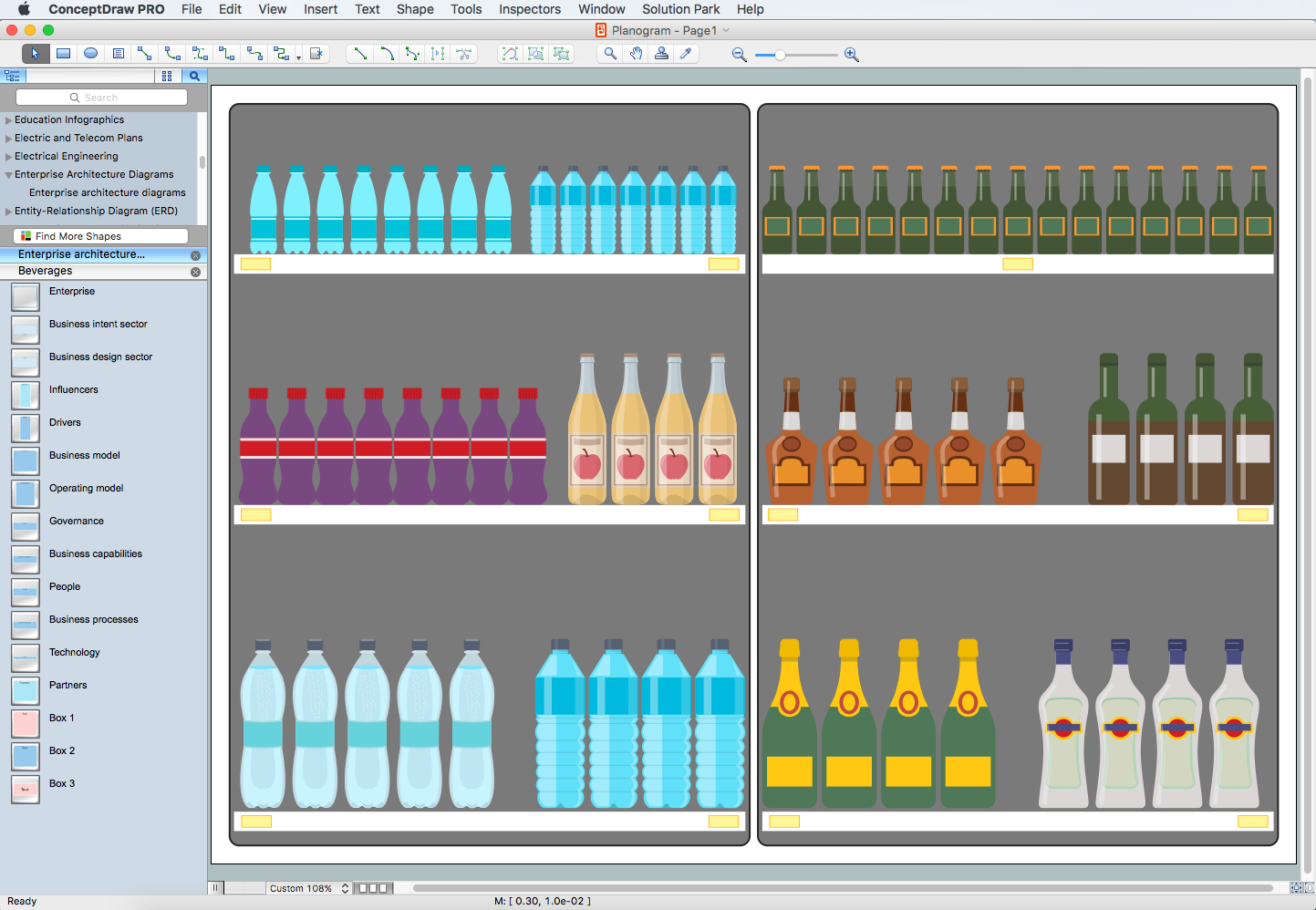
Planogram Software and Retail Plan Software
- Restaurant For Use Case Diagram And Data Flow Diagram
- Data Flow Diagram Of Restaurant System In Software Engineering
- Data Flow Diagrams (DFD) | Jacobson Use Cases Diagram ...
- Use Case Diagram And Dfd For Restaurant System
- Usecase Diagram For Restaurant System
- Use Case And Data Flow Diagram For Restaurant System
- Draw Use Case And Data Flow Diagram For A Restaurant System
- Process Flowchart | UML Diagram | Data Flow Diagram | Diagrams ...
- UML Use Case Diagram Example Registration System | Entity ...
- Dfd Diagram For Restaurant Management System
- Use Case Diagram For E Restaurant System
- Jacobson Use Cases Diagram | Systems Engineering | Data Flow ...
- UML Deployment Diagram Example - ATM System UML diagrams ...
- Data Flow Diagram In Restaurant System
- Data Flow Diagrams (DFD) | Gym and Spa Area Plans | Cafe and ...
- UML Diagram | Bank System | Data Flow Diagrams (DFD) | Diagram ...
- Data Flow Diagrams (DFD) | Cafe and Restaurant Floor Plans ...
- Jacobson Use Cases Diagram | Systems Engineering | Data Flow ...
- Data Flow Diagrams (DFD) | Entity-Relationship Diagram (ERD ...
- Example of DFD for Online Store ( Data Flow Diagram ) DFD ...
- ERD | Entity Relationship Diagrams, ERD Software for Mac and Win
- Flowchart | Basic Flowchart Symbols and Meaning
- Flowchart | Flowchart Design - Symbols, Shapes, Stencils and Icons
- Flowchart | Flow Chart Symbols
- Electrical | Electrical Drawing - Wiring and Circuits Schematics
- Flowchart | Common Flowchart Symbols
- Flowchart | Common Flowchart Symbols