Use Case Diagrams technology with ConceptDraw PRO

ConceptDraw Arrows10 Technology

Using any other connection point provides a static connection, when you move connected objects the connector stays attached to the same point.
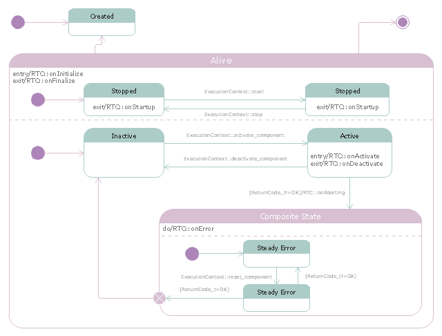
"RT-middleware (Robotics Technology Middleware) is a common platform standards for Robots based on the distributed object technology. RT-middleware supports the construction of various networked robotic systems by the integration of various network enabled robotic elements called RT-Components. The specification standard of the RT-component is discussed / defined by the Object Management Group (OMG). ...
In the RT-middleware, robotics elements, such as actuators, are regarded as RT-components, and the whole robotic system is constructed by connecting those RT-components. This distributed architecture helps developers to re-use the robotic elements, and boosts the reliability of the robotic system.
Each RT-component has port as an endpoint for communicating other RT-components. Every port has its type and the ports which have the same type can be connected each other.
RT-components also has its state, so the RT-components behaves as state machines. The states that RT-components can have are CREATED, INACTIVE, ACTIVE, and ERROR, and the states and behaviors are controlled by the execution-context. If developers want to change the behavior of their RT-components, the execution-context can be replaced at run-time." [RT middleware. Wikipedia]
The UML state machine diagram example "State transitions of RT-component" was created using the ConceptDraw PRO diagramming and vector drawing software extended with the Rapid UML solution from the Software Development area of ConceptDraw Solution Park.
UML state machine diagram
Business Graphics and Diagramming Package

You don't have to guide your connectors, they do this automatically.
Get software for creating business graphics such as charts and graphs, diagrams, organizational charts, multimedia presentations, and visual demonstrations.
ConceptDraw Arrows10 Technology

The magic of ConceptDraw Arrows10’s rotating group containing connectors, makes complex diagramming simple and easy.
The way to connect objects has never been easier.
HelpDesk
How to Create a UML Diagram Using ConceptDraw PRO

Cross-Functional Flowcharts in ConceptDraw

Create Sophisticated Professional Diagrams - Simply

- UML Business Process | Business Process Modeling with ...
- Use Case Diagrams technology with ConceptDraw PRO ...
- Use Case Diagrams technology with ConceptDraw PRO
- Use Case Diagrams technology with ConceptDraw PRO | UML Use ...
- UML Use Case Diagram Example Registration System | Use Case ...
- Use Case Diagrams technology with ConceptDraw PRO | Rapid ...
- UML Use Case Diagram Example Registration System | Use Case ...
- UML activity diagram - Snap in process | ConceptDraw Arrows10 ...
- Use Case Diagrams technology with ConceptDraw PRO | UML Use ...
- Use Case Diagrams technology with ConceptDraw PRO | Financial ...
- UML Diagram | Use Case Diagrams technology with ConceptDraw ...
- Rapid UML | Use Case Diagrams technology with ConceptDraw ...
- UML Use Case Diagram. Design Elements
- UML Diagrams with ConceptDraw PRO | Use Case Diagrams ...
- Use Case Diagrams technology with ConceptDraw PRO | UML Use ...
- UML Use Case Diagram Example Registration System | Use Case ...
- UML Class Diagram Tutorial | Use Case Diagrams technology with ...
- UML Use Case Diagrams | Use Case Diagrams technology with ...
- Diagramming Software for Design UML Use Case Diagrams
- Use Case Diagrams technology with ConceptDraw PRO | UML ...
- ERD | Entity Relationship Diagrams, ERD Software for Mac and Win
- Flowchart | Basic Flowchart Symbols and Meaning
- Flowchart | Flowchart Design - Symbols, Shapes, Stencils and Icons
- Flowchart | Flow Chart Symbols
- Electrical | Electrical Drawing - Wiring and Circuits Schematics
- Flowchart | Common Flowchart Symbols
- Flowchart | Common Flowchart Symbols