"RT-middleware (Robotics Technology Middleware) is a common platform standards for Robots based on the distributed object technology. RT-middleware supports the construction of various networked robotic systems by the integration of various network enabled robotic elements called RT-Components. The specification standard of the RT-component is discussed / defined by the Object Management Group (OMG). ...
In the RT-middleware, robotics elements, such as actuators, are regarded as RT-components, and the whole robotic system is constructed by connecting those RT-components. This distributed architecture helps developers to re-use the robotic elements, and boosts the reliability of the robotic system.
Each RT-component has port as an endpoint for communicating other RT-components. Every port has its type and the ports which have the same type can be connected each other.
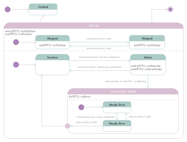
RT-components also has its state, so the RT-components behaves as state machines. The states that RT-components can have are CREATED, INACTIVE, ACTIVE, and ERROR, and the states and behaviors are controlled by the execution-context. If developers want to change the behavior of their RT-components, the execution-context can be replaced at run-time." [RT middleware. Wikipedia]
The UML state machine diagram example "State transitions of RT-component" was created using the ConceptDraw PRO diagramming and vector drawing software extended with the Rapid UML solution from the Software Development area of ConceptDraw Solution Park.
In the RT-middleware, robotics elements, such as actuators, are regarded as RT-components, and the whole robotic system is constructed by connecting those RT-components. This distributed architecture helps developers to re-use the robotic elements, and boosts the reliability of the robotic system.
Each RT-component has port as an endpoint for communicating other RT-components. Every port has its type and the ports which have the same type can be connected each other.
RT-components also has its state, so the RT-components behaves as state machines. The states that RT-components can have are CREATED, INACTIVE, ACTIVE, and ERROR, and the states and behaviors are controlled by the execution-context. If developers want to change the behavior of their RT-components, the execution-context can be replaced at run-time." [RT middleware. Wikipedia]
The UML state machine diagram example "State transitions of RT-component" was created using the ConceptDraw PRO diagramming and vector drawing software extended with the Rapid UML solution from the Software Development area of ConceptDraw Solution Park.
UML state machine diagram
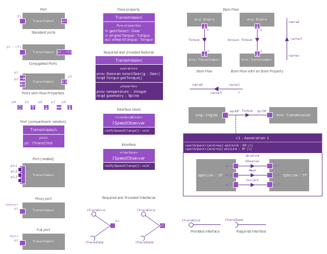
The vector stencils library "Ports and Flows" contains 26 SysML symbols.
Use it to design your SysML diagrams using ConceptDraw PRO diagramming and vector drawing software.
"The main motivation for specifying ports and flows is to enable design of modular, reusable blocks with clearly defined
ways of connecting and interacting with their context of use. This clause extends UML ports to support nested ports, and
extends blocks to support flow properties, and required and provided features, including blocks that type ports. Ports can be typed by blocks that support operations, receptions, and properties as in UML. SysML defines a specialized form of Block (InterfaceBlock) that can be used to support nested ports. SysML identifies two kinds of ports, one that exposes
features of the owning block or its internal parts (proxy ports), and another that supports its own features (full ports). Default compatibility rules are defined for connecting blocks used in composite structure, including parts and ports, with association blocks available to define more specific ways of doing this. These additional capabilities in SysML enable modelers to specify a wide variety of interconnectable components, which can be implemented through many engineering and social techniques, such as software, electrical or mechanical components, and human organizations. This clause also extends UML information flows for specifying item flows across connectors and associations." [www.omg.org/ spec/ SysML/ 1.3/ PDF]
The SysML shapes example "Design elements - Ports and Flows" is included in the SysML solution from the Software Development area of ConceptDraw Solution Park.
SysML ports and flows symbols
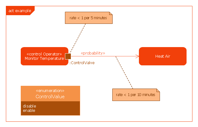
This example was drawn on the base of SysML activity diagram on the page 8 of "SysML Modelling Language explained" document from the Official OMG SysML site.
"The activity diagram represents steps of a process, often making use of “input and output pins” that respectively correspond to the element type required as the input of an activity or action, and the element generated as an output.
If an action or activity corresponds to a block operation, it is possible to ensure that the types of the input and output of this activity are consistent with the block operation signature.
All the activity diagrams definitions used in UML also apply to SysML.
SysML has added a couple of extensions:
- With UML, control can only enable actions to start. SysML extends control to support disabling of actions that are already executing.
- Definition of the flow rate : continuous or discrete
- Definition of the rate and probability on the control or object flows"
[omgsysml.org/ SysML_ Modelling_ Language_ explained-finance.pdf]
The example "SysML activity diagram" was drawn using the ConceptDraw PRO diagramming and vector drawing software extended with the SysML solution from the Software Development area of ConceptDraw Solution Park.
Example of SysML activity diagram
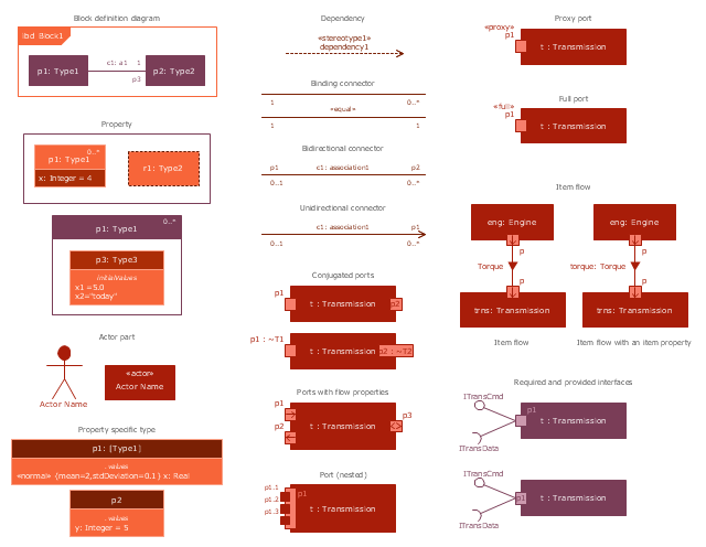
The vector stencils library "Internal block diagram" contains 22 SysML symbols.
Use it to design your internal block diagrams using ConceptDraw PRO diagramming and vector drawing software.
"Internal Block Diagram
An internal block diagram is based on the UML composite structure diagram, with restrictions and extensions as defined
by SysML. ...
Property types
Four general categories of properties of blocks are recognized in SysML: parts, references, value properties, and
constraint properties. ... A part or value property is always shown on an internal block diagram with a solid-outline box. A reference property is shown by a dashed-outline box, consistent with UML. Ports are special cases of properties, and have a variety of notations... Constraint properties and their parameters also have their own notations... " [www.omg.org/ spec/ SysML/ 1.3/ PDF]
The SysML shapes example "Design elements - Internal block diagram" is included in the SysML solution from the Software Development area of ConceptDraw Solution Park.
Internal block diagram symbols
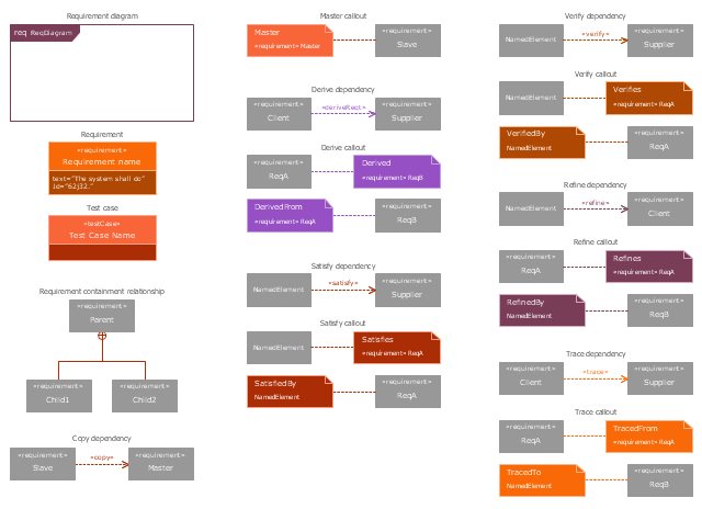
The vector stencils library "Requirement diagram" contains 21 SysML symbols.
Use it to design your requirement diagrams using ConceptDraw PRO diagramming and vector drawing software.
"A requirement specifies a capability or condition that must (or should) be satisfied. A requirement may specify a function that a system must perform or a performance condition a system must achieve. SysML provides modeling constructs to represent text-based requirements and relate them to other modeling elements. The requirements diagram described in this clause can depict the requirements in graphical, tabular, or tree structure format. A requirement can also appear on other diagrams to show its relationship to other modeling elements. The requirements modeling constructs are intended to provide a bridge between traditional requirements management tools and the other SysML models.
A requirement is defined as a stereotype of UML Class subject to a set of constraints. A standard requirement includes properties to specify its unique identifier and text requirement. Additional properties such as verification status, can be specified by the user.
Several requirements relationships are specified that enable the modeler to relate requirements to other requirements as well as to other model elements. These include relationships for defining a requirements hierarchy, deriving requirements, satisfying requirements, verifying requirements, and refining requirements." [www.omg.org/ spec/ SysML/ 1.3/ PDF]
The SysML shapes example "Design elements - Requirement diagram" is included in the SysML solution from the Software Development area of ConceptDraw Solution Park.
SysML requirement diagram symbols
- Omg Uml
- Uml Omg
- Introductory Guide to Rapid UML Solution | UML state machine ...
- Design elements - Bank UML profile diagram | Design elements ...
- UML state machine diagram - State transitions of RT-component ...
- Diagramming Software for Design UML State Machine Diagrams ...
- Rapid UML | Design elements - Ports and Flows | ATM UML ...
- Design elements - Ports and Flows | Types of Flowcharts | Standard ...
- UML Class Diagram Generalization Example UML Diagrams
- UML State Machine Diagram.Design Elements | Workflow Diagram ...
- UML state machine diagram - Template | Diagramming Software for ...
- UML Block Diagram
- UML State Machine Diagram.Design Elements
- UML Class Diagram Generalization Example UML Diagrams ...
- UML Diagram | Process Flowchart | How to Edit Grouped Shapes in ...
- UML Class Diagram Notation
- Jacobson Use Cases Diagram | Use case restaurant model | UML ...
- UML Component Diagram. Design Elements | UML Diagram ...
- Design elements - Internal block diagram | UML Diagram | UML ...
- State machine diagram | Diagramming Software for Design UML ...
- ERD | Entity Relationship Diagrams, ERD Software for Mac and Win
- Flowchart | Basic Flowchart Symbols and Meaning
- Flowchart | Flowchart Design - Symbols, Shapes, Stencils and Icons
- Flowchart | Flow Chart Symbols
- Electrical | Electrical Drawing - Wiring and Circuits Schematics
- Flowchart | Common Flowchart Symbols
- Flowchart | Common Flowchart Symbols