UML Class Diagram Generalization Example UML Diagrams

This sample describes the use of the classes, the generalization associations between them, the multiplicity of associations and constraints. Provided UML diagram is one of the examples set that are part of Rapid UML solution.
UML Use Case Diagram Example. Services UML Diagram. ATM system

This sample shows the scheme of the servicing using the ATMs (Automated Teller Machines) and is used at the working of ATM banking systems, at the performing of the banking transactions.
ERD Symbols and Meanings

The Chen's ERD notation is still used and is considered to present a more detailed way of representing entities and relationships.
To create an ERD, software engineers mainly turn to dedicated drawing software, which contain the full notation resources for their specific database design - ERD symbols and meanings. CS Odessa has released an all-inclusive Entity-Relationship Diagram (ERD) solution for their powerful drawing program, ConceptDraw DIAGRAM.

UML Diagram

Create unified modeling language (UML) diagrams with ConceptDraw.
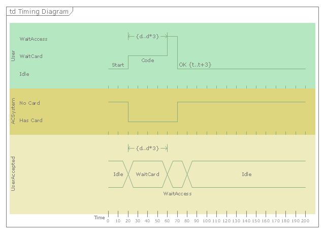
The vector stencils library "Bank UML timing diagram" contains 8 shapes for drawing UML timing diagrams.
Use it for object-oriented modeling of your bank information system.
"A timing diagram in the Unified Modeling Language 2.0 is a specific type of interaction diagram, where the focus is on timing constraints.
Timing diagrams are used to explore the behaviors of objects throughout a given period of time. A timing diagram is a special form of a sequence diagram. The differences between timing diagram and sequence diagram are the axes are reversed so that the time is increased from left to right and the lifelines are shown in separate compartments arranged vertically.
There are two basic flavors of timing diagram: the concise notation, and the robust notation." [Timing diagram. Wikipedia]
This example of UML timing diagram symbols for the ConceptDraw PRO diagramming and vector drawing software is included in the ATM UML Diagrams solution from the Software Development area of ConceptDraw Solution Park.
UML timing diagram symbols
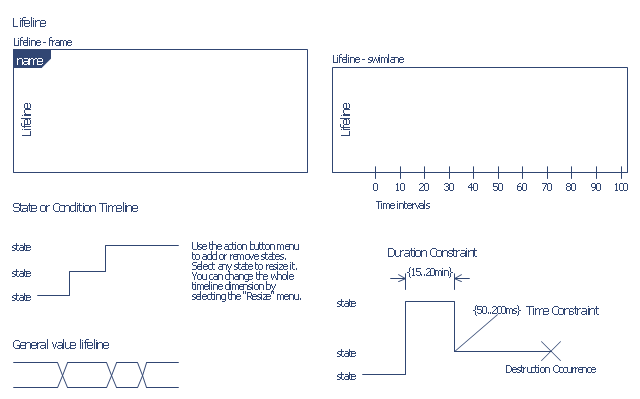
"A timing diagram in the Unified Modeling Language 2.0 is a specific type of interaction diagram, where the focus is on timing constraints.
Timing diagrams are used to explore the behaviors of objects throughout a given period of time. A timing diagram is a special form of a sequence diagram. The differences between timing diagram and sequence diagram are the axes are reversed so that the time is increased from left to right and the lifelines are shown in separate compartments arranged vertically.
There are two basic flavors of timing diagram: the concise notation, and the robust notation." [Timing diagram (Unified Modeling Language). Wikipedia]
This UML timing diagram example was created using the ConceptDraw PRO diagramming and vector drawing software extended with the Rapid UML solution from the Software Development area of ConceptDraw Solution Park.
UML timing diagram
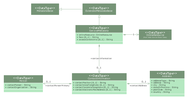
"Metadata is "data about data". The term is ambiguous, as it is used for two fundamentally different concepts (types). Structural metadata is about the design and specification of data structures and is more properly called "data about the containers of data"; descriptive metadata, on the other hand, is about individual instances of application data, the data content.
Metadata are traditionally found in the card catalogs of libraries. As information has become increasingly digital, metadata are also used to describe digital data using metadata standards specific to a particular discipline. By describing the contents and context of data files, the quality of the original data/ files is greatly increased. For example, a webpage may include metadata specifying what language it is written in, what tools were used to create it, and where to go for more on the subject, allowing browsers to automatically improve the experience of users." [Metadata. Wikipedia]
The UML class diagram example "Metadata information model" was created using the ConceptDraw PRO diagramming and vector drawing software extended with the Rapid UML solution from the Software Development area of ConceptDraw Solution Park.
UML class diagram
"Crow's Foot notation is used in Barker's Notation, SSADM and Information Engineering. Crow's Foot diagrams represent entities as boxes, and relationships as lines between the boxes. Different shapes at the ends of these lines represent the cardinality of the relationship." [Entity–relationship model. Wikipedia]
The vector stencils library ERD, crow's foot notation contains 18 symbols for creating the ER-diagrams using the ConceptDraw PRO diagramming nd vector drawing software.
The example"Design elements - ERD solution (crow's foot notation)" is included in the Entity-Relationship Diagram (ERD) solution from the Software Development area of ConceptDraw Solution Park.
Crow's foot ERD
.png--diagram-flowchart-example.png)
Design Elements for UML Diagrams

About UML

This sample shows the work of the taxi service and is used by taxi stations, by airports, in the tourism field and delivery service.
- Object Oriented Dfd Wiki
- UML interaction overview diagram - Template | Design elements ...
- Purchase order processing UML activity diagram | UML class ...
- UML use case diagram - Banking system | Class UML Diagram for ...
- UML use case diagram - System of goods selling via catalogues ...
- Design elements - UML activity diagrams | UML activity diagram ...
- Er Diagram And Its Various Notation In Wikipedia
- Definition Flowchart | ERD Symbols and Meanings | Data Flow ...
- UML Deployment Diagram . Diagramming Software for Design UML ...
- Procurement process mapping | UML Business Process | Pyramid ...
- ERD | Entity Relationship Diagrams, ERD Software for Mac and Win
- Flowchart | Basic Flowchart Symbols and Meaning
- Flowchart | Flowchart Design - Symbols, Shapes, Stencils and Icons
- Flowchart | Flow Chart Symbols
- Electrical | Electrical Drawing - Wiring and Circuits Schematics
- Flowchart | Common Flowchart Symbols
- Flowchart | Common Flowchart Symbols