 Rapid UML
Rapid UML solution extends ConceptDraw PRO software with templates, samples and libraries of vector stencils for quick drawing the UML diagrams using Rapid Draw technology.
HelpDesk
How to Make a UML Diagram in ConceptDraw PRO

Using UML during the modeling process has a number of benefits — for one, the entire development team can share information and collaborate using common language, diagrams and software, something that's not possible when using a more task-specific programming language.
It allows team members to create system 'blueprin
HelpDesk
How to Create a UML Diagram Using ConceptDraw PRO

HelpDesk
How to Create a Bank ATM Use Case Diagram

ConceptDraw PRO diagramming software, enhanced and expanded with the ATM UML Diagrams solution, offers the full range of icons, templates and design elements needed to faithfully represent ATM and banking information system architecture using UML standards. The ATM UML Diagrams solution is useful for beginner and advanced users alike. More experienced users will appreciate a full range of vector stencil libraries and ConceptDraw PRO's powerful software, that allows you to create your ATM UML diagram in a matter of moments.
 Rapid UML
Rapid UML solution extends ConceptDraw PRO software with templates, samples and libraries of vector stencils for quick drawing the UML diagrams using Rapid Draw technology.
This purchase order processing UML activity diagram was created on the base of activity diagram from the software architecture documentation wiki of the Software Engineering Institute (SEI) of Carnegie Mellon University (CMU).
[wiki.sei.cmu.edu/ sad/ index.php/ Image:PurchaseOrderActivityDiagram.png]
"A purchase order (PO) is a commercial document and first official offer issued by a buyer to a seller, indicating types, quantities, and agreed prices for products or services. Acceptance of a purchase order by a seller forms a contract between the buyer and seller, so no contract exists until the purchase order is accepted. It is used to control the purchasing of products and services from external suppliers.
Creating a purchase order is typically the first step of the purchase to pay process in an ERP system." [Purchase order. Wikipedia]
This purchase order processing UML activity diagram example was created using the ConceptDraw PRO diagramming and vector drawing software extended with the ATM UML Diagrams solution from the Software Development area of ConceptDraw Solution Park.
UML activity diagram of purchase order processing

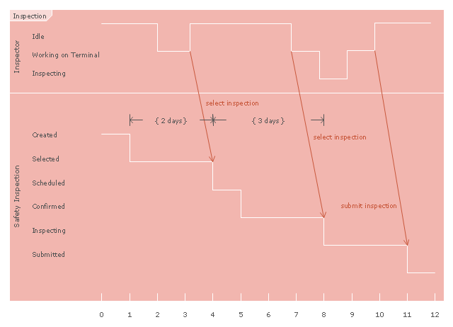
"Inspection in software engineering, refers to peer review of any work product by trained individuals who look for defects using a well defined process. An inspection might also be referred to as a Fagan inspection after Michael Fagan, the creator of a very popular software inspection process. ...
An inspection is one of the most common sorts of review practices found in software projects. The goal of the inspection is for all of the inspectors to reach consensus on a work product and approve it for use in the project. Commonly inspected work products include software requirements specifications and test plans. In an inspection, a work product is selected for review and a team is gathered for an inspection meeting to review the work product. A moderator is chosen to moderate the meeting. Each inspector prepares for the meeting by reading the work product and noting each defect. The goal of the inspection is to identify defects. In an inspection, a defect is any part of the work product that will keep an inspector from approving it. For example, if the team is inspecting a software requirements specification, each defect will be text in the document which an inspector disagrees with." [Software inspection. Wikipedia]
The UML timing diagram example "Inspection" was created using the ConceptDraw PRO diagramming and vector drawing software extended with the Rapid UML solution from the Software Development area of ConceptDraw Solution Park.
UML timing diagram
- UML Diagrams with ConceptDraw PRO | ConceptDraw Solution ...
- UML Diagrams with ConceptDraw PRO | UML sequence diagram ...
- UML Class Diagram Example - Social Networking Site | UML Class ...
- UML Use Case Diagram Example Social Networking Sites Project ...
- UML Component Diagram Example - Online Shopping | UML Tool ...
- UML Diagram Visio | In searching of alternative to MS Visio for MAC ...
- UML Deployment Diagram
- UML Class Diagram Example for Transport System | UML ...
- Taxi Service Data Flow Diagram DFD Example | UML Use Case ...
- UML Package Diagram | Diagramming Software for Design UML ...
- Rapid UML | Introductory Guide to Rapid UML Solution | UML ...
- How to Draw a Computer Network Diagrams | UML Diagrams with ...
- Diagramming Software for Design UML State Machine Diagrams ...
- UML Block Diagram | Diagramming Software for Design UML ...
- UML Diagram Types List | UML Notation | UML Diagrams with ...
- UML Component Diagram Example - Online Shopping | State ...
- Organizational Chart Templates | UML composite structure diagram ...
- UML Diagrams with ConceptDraw PRO | UML Component Diagram ...
- Rapid UML | Flowchart Software | Rapid UML | Visio Sequence ...
- Diagramming Software for Design UML Collaboration Diagrams ...
- ERD | Entity Relationship Diagrams, ERD Software for Mac and Win
- Flowchart | Basic Flowchart Symbols and Meaning
- Flowchart | Flowchart Design - Symbols, Shapes, Stencils and Icons
- Flowchart | Flow Chart Symbols
- Electrical | Electrical Drawing - Wiring and Circuits Schematics
- Flowchart | Common Flowchart Symbols
- Flowchart | Common Flowchart Symbols