"Component diagram shows components, provided and required interfaces, ports, and relationships between them. This type of diagrams is used in Component-Based Development (CBD) to describe systems with Service-Oriented Architecture (SOA).
Component-based development is based on assumptions that previously constructed components could be reused and that components could be replaced by some other "equivalent" or "conformant" components, if needed.
The artifacts that implement component are intended to be capable of being deployed and re-deployed independently, for instance to update an existing system.
Components in UML could represent:
(1) logical components (e.g., business components, process components), and
(2) physical components (e.g., CORBA components, EJB components, COM+ and .NET components, WSDL components, etc.),
along with the artifacts that implement them and the nodes on which they are deployed and executed. It is anticipated that profiles based around components will be developed for specific component technologies and associated hardware and software environments." [uml-diagrams.org/ component-diagrams.html]
The template "UML component diagram" for the ConceptDraw PRO diagramming and vector drawing software is included in the Rapid UML solution from the Software Development area of ConceptDraw Solution Park.
www.conceptdraw.com/ solution-park/ software-uml
UML component diagram

UML Deployment Diagram Example - ATM System UML diagrams

This sample shows the work of the ATM (Automated Teller Machine) banking system that is used for service and performing of the banking transactions using ATMs. System engineers can use comprehensive UML diagrams solution.
UML Activity Diagram. Design Elements


 Rapid UML
Rapid UML solution extends ConceptDraw DIAGRAM software with templates, samples and libraries of vector stencils for quick drawing the UML diagrams using Rapid Draw technology.
 Rapid UML
Rapid UML solution extends ConceptDraw DIAGRAM software with templates, samples and libraries of vector stencils for quick drawing the UML diagrams using Rapid Draw technology.
UML Notation

Two types of diagrams are used in UML: Structure Diagrams and Behavior Diagrams. Behavior Diagrams represent the processes proceeding in a modeled environment. Structure Diagrams represent the elements that compose the system.
UML Class Diagram Example - Social Networking Site
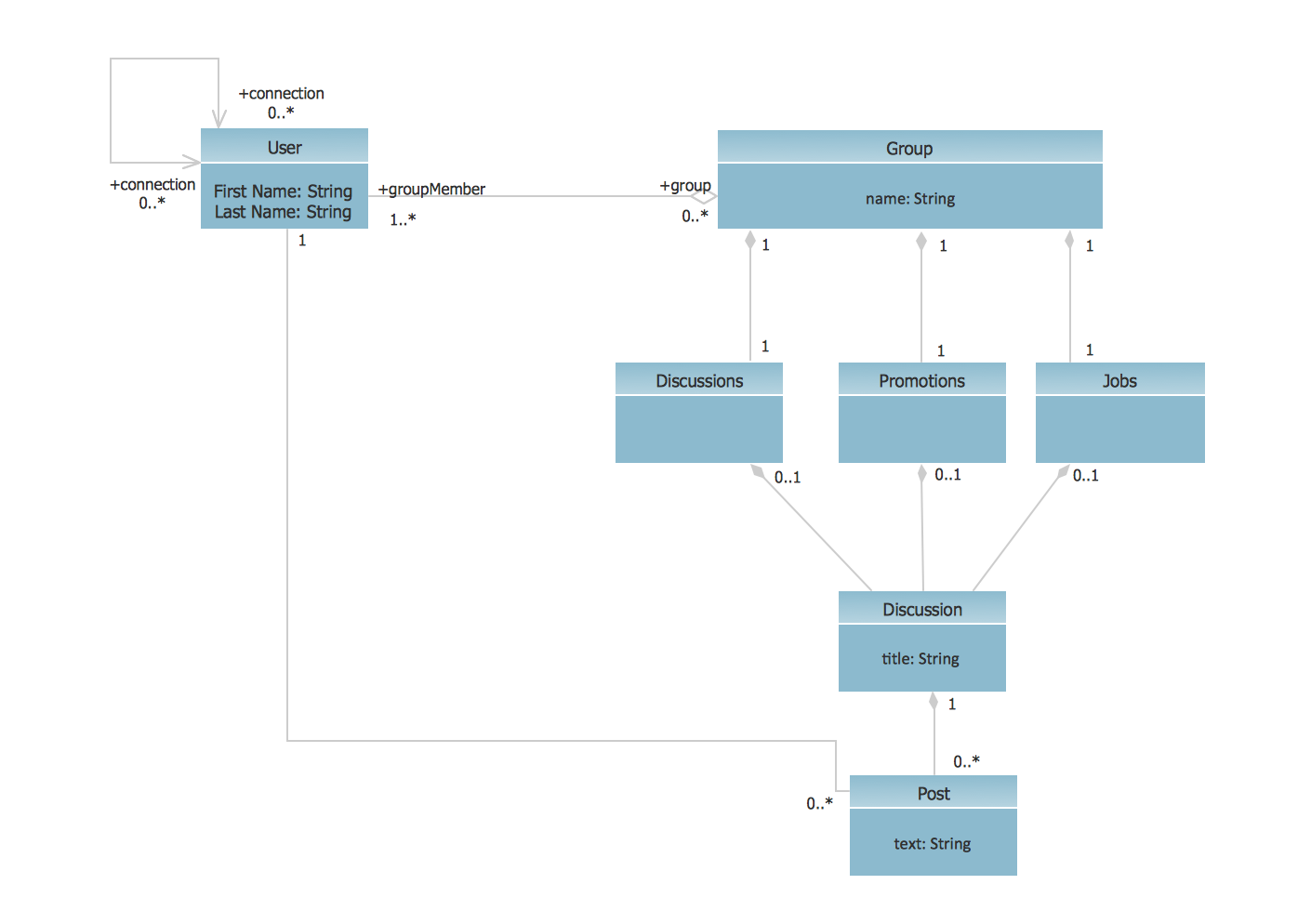
This sample shows the structure of the popular social networking site Linkedin and is used in the business field, in IT, at the projection and creating of the social networking sites.
 Entity-Relationship Diagram (ERD)
Entity-Relationship Diagram (ERD) solution extends ConceptDraw DIAGRAM software with templates, samples and libraries of vector stencils from drawing the ER-diagrams by Chen's and crow’s foot notations.
 Cisco Network Diagrams
Cisco Network Diagrams solution extends ConceptDraw DIAGRAM with the best characteristics of network diagramming software. Included samples, templates and libraries of built-in standardized vector Cisco network icons and Cisco symbols of computers, network devices, network appliances and other Cisco network equipment will help network engineers, network designers, network and system administrators, as well as other IT professionals and corporate IT departments to diagram efficiently the network infrastructure, to visualize computer networks topologies, to design Cisco computer networks, and to create professional-looking Cisco Computer network diagrams, Cisco network designs and schematics, Network maps, and Network topology diagrams in minutes.
 Enterprise Architecture Diagrams
Enterprise Architecture Diagrams solution extends ConceptDraw DIAGRAM software with templates, samples and library of vector stencils for drawing the diagrams of enterprise architecture models.
 Computer Network Diagrams
Computer Network Diagrams solution extends ConceptDraw DIAGRAM software with samples, templates and libraries of vector icons and objects of computer network devices and network components to help you create professional-looking Computer Network Diagrams, to plan simple home networks and complex computer network configurations for large buildings, to represent their schemes in a comprehensible graphical view, to document computer networks configurations, to depict the interactions between network's components, the used protocols and topologies, to represent physical and logical network structures, to compare visually different topologies and to depict their combinations, to represent in details the network structure with help of schemes, to study and analyze the network configurations, to communicate effectively to engineers, stakeholders and end-users, to track network working and troubleshoot, if necessary.
 Project Exchange
This solution extends ConceptDraw PROJECT and ConceptDraw MINDMAP software with the ability to import and export project data.
- UML Activity Diagram. Design Elements | UML component diagram ...
- UML Deployment Diagram. Diagramming Software for Design UML ...
- Diagramming Software for Design UML Component Diagrams | UML ...
- UML component diagram
- UML component diagram - Template | UML deployment diagram ...
- Process Flowchart | UML component diagram - Template | UML ...
- UML Component Diagram | Flowchart Components | Process ...
- UML component diagram - Template | Process Flowchart | UML ...
- UML Deployment Diagram. Design Elements | UML component ...
- UML Component Diagram. Design Elements | UML Deployment ...
- UML Component Diagram | UML component diagram - Template ...
- UML Deployment Diagram. Design Elements | Process Flowchart ...
- UML Deployment Diagram. Diagramming Software for Design UML ...
- UML Component Diagram Example - Online Shopping | UML ...
- UML Tool & UML Diagram Examples | UML Component Diagram ...
- UML Component Diagram | Diagramming Software for Design UML ...
- UML package diagram - Template | UML communication diagram ...
- UML Diagram | AWS Architecture Diagrams | UML component ...
- AWS Architecture Diagrams | UML component diagram - Start server ...
- Process Flowchart | UML Deployment Diagram. Design Elements ...
- ERD | Entity Relationship Diagrams, ERD Software for Mac and Win
- Flowchart | Basic Flowchart Symbols and Meaning
- Flowchart | Flowchart Design - Symbols, Shapes, Stencils and Icons
- Flowchart | Flow Chart Symbols
- Electrical | Electrical Drawing - Wiring and Circuits Schematics
- Flowchart | Common Flowchart Symbols
- Flowchart | Common Flowchart Symbols