Mechanical Drawing Symbols

Process Flow Diagram

ConceptDraw PRO diagramming and vector drawing software extended with powerful tools of Flowcharts Solution from the "Diagrams" Area of ConceptDraw Solution Park is effective for drawing: Process Flow Diagram, Flow Process Diagram, Business Process Flow Diagrams.
Process Flowchart


Process Flow Diagram Symbols

Process Flow Chart

ConceptDraw PRO diagramming and vector drawing software extended with Flowcharts Solution from the "Diagrams" Area of ConceptDraw Solution Park is the best way to create Process Flow Chart and other types of flowcharts.
 Mechanical Engineering
This solution extends ConceptDraw PRO v.9 mechanical drawing software (or later) with samples of mechanical drawing symbols, templates and libraries of design elements, for help when drafting mechanical engineering drawings, or parts, assembly, pneumatic,
Process Engineering

Process Diagrams

Pipe Bender Plans

HVAC Business Plan

Chemical Engineering

Electric Visual


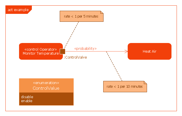
This example was drawn on the base of SysML activity diagram on the page 8 of "SysML Modelling Language explained" document from the Official OMG SysML site.
"The activity diagram represents steps of a process, often making use of “input and output pins” that respectively correspond to the element type required as the input of an activity or action, and the element generated as an output.
If an action or activity corresponds to a block operation, it is possible to ensure that the types of the input and output of this activity are consistent with the block operation signature.
All the activity diagrams definitions used in UML also apply to SysML.
SysML has added a couple of extensions:
- With UML, control can only enable actions to start. SysML extends control to support disabling of actions that are already executing.
- Definition of the flow rate : continuous or discrete
- Definition of the rate and probability on the control or object flows"
[omgsysml.org/ SysML_ Modelling_ Language_ explained-finance.pdf]
The example "SysML activity diagram" was drawn using the ConceptDraw PRO diagramming and vector drawing software extended with the SysML solution from the Software Development area of ConceptDraw Solution Park.
Example of SysML activity diagram
HelpDesk
How to Draw a Chemical Process Flow Diagram

- Types Of Valves Pdf
- Industrial Valves Types Pdf
- Hydraulic Valves Pdf
- Mechanical Engineering Valves Pdf
- Valve Symbols Pdf
- Diagrams Of Types Of Valves In A Refinery
- Industrial Valve Symbols Pdf
- Valve Assembly Drawing Pdf
- Types Of Valve And Symbols For Piping
- Insuatrial Important Piping Valve Symbols Pdf
- Ppt Of Types Valve For Chemical Engineering Pdf
- Valve For Mechanical Engineering Pdf File
- Types Of Welding Joints Pdf
- Mechanical Valve Drafting Pdf
- Chemical Plant All Types Equipment Symbol Pdf Files
- Fitting Valve Symbol Pdf
- Drawing Sketches Of Different Types Of Valve
- Download The Types Of Valves And Joint In Plumbing Ppt
- Process Flow Diagram Symbols | Design elements - Valves and ...
- Fluid Power Symbols Of Valves Pdf
- ERD | Entity Relationship Diagrams, ERD Software for Mac and Win
- Flowchart | Basic Flowchart Symbols and Meaning
- Flowchart | Flowchart Design - Symbols, Shapes, Stencils and Icons
- Flowchart | Flow Chart Symbols
- Electrical | Electrical Drawing - Wiring and Circuits Schematics
- Flowchart | Common Flowchart Symbols
- Flowchart | Common Flowchart Symbols