Create Floor Plans Easily with ConceptDraw DIAGRAM

Primarily, this basic knowledge of the composition rules. It helps to compose, to place the shapes and volume of the interior, to achieve balance in the room between the free space and objects. This might help to compose correctly, to place the shapes and the volumes in the interior, to achieve balance between free space and furniture in the room.
Basic color theory. There are strictly defined rules and laws, which are used to select a fitting color combinations to create a harmonious interior.

Cross-Functional Flowchart

Use cross-functional flowcharts to show the relationship between a business process and the functional units (such as departments) responsible for that process. To create it use the best flowchart maker of ConceptDraw DIAGRAM.

Best Value Stream Mapping mac Software

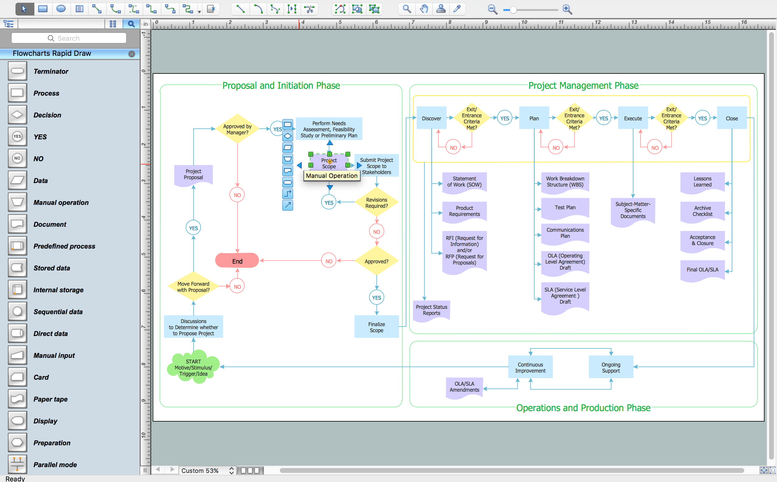
How To Create a FlowChart using ConceptDraw
UML Use Case Diagram. Design Elements


Diagramming Software for Design UML Use Case Diagrams

UML Deployment Diagram
Use ConceptDraw DIAGRAM with UML deployment diagram templates, samples and stencil library from Rapid UML solution to model the physical deployment of artifacts on nodes of your software system.
Flowchart Definition

UML Sequence Diagram. Design Elements

Cisco IBM. Cisco icons, shapes, stencils and symbols

- 3d Trade Show Booth Design Software Free
- Store Layout Software | Planogram Software and Retail Plan ...
- Trade Show Display Design Template
- Electrical Drawing Software and Electrical Symbols
- How To Create a MS Visio Business Process Diagram Using ...
- How to Draw an Organization Chart | Marketing and Sales ...
- Trade Show Layout Ideas
- Process Flowchart | Design elements - Workflow finance | Basic ...
- Restaurant Floor Plans Software | How To Create Restaurant Floor ...
- Basic Flowchart Symbols and Meaning | Cross Functional Flowchart ...
- ERD | Entity Relationship Diagrams, ERD Software for Mac and Win
- Flowchart | Basic Flowchart Symbols and Meaning
- Flowchart | Flowchart Design - Symbols, Shapes, Stencils and Icons
- Flowchart | Flow Chart Symbols
- Electrical | Electrical Drawing - Wiring and Circuits Schematics
- Flowchart | Common Flowchart Symbols
- Flowchart | Common Flowchart Symbols