Process Flowchart


Cross-Functional Flowchart

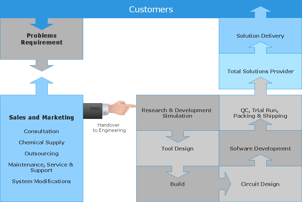
Use cross-functional flowcharts to show the relationship between a business process and the functional units (such as departments) responsible for that process. To create it use the best flowchart maker of ConceptDraw PRO.

Network diagrams with ConceptDraw PRO

Network diagrams are divided into Physical Network Diagrams and Logical Network Diagrams.
Network diagram is an indispensable tool for network administrators and engineers at development of new networks and management of existing networks.
Flowchart Programming Project. Flowchart Examples

The programming project flow chart example shows the logical process of execution.
Data Modeling with Entity Relationship Diagram

The best ERD tool for the Mac and Windows is ConceptDraw PRO software extended with the Entity-Relationship Diagram (ERD) solution from the Software Development Area for ConceptDraw Solution Park, which is sharpened for professional ERD drawing and data modeling with Entity Relationship Diagram.
Hotel Plan. Hotel Plan Examples

Use ConceptDraw PRO diagramming and vector drawing software enhanced with Building Plans solution to draw your own site and floor plans, design and layouts.
Best Vector Drawing Application for Mac OS X
 Venn Diagrams
Venn Diagrams are actively used to illustrate simple set relationships in set theory and probability theory, logic and statistics, mathematics and computer science, linguistics, sociology, and marketing. Venn Diagrams are also often used to visually summarize the status and future viability of a project.
Work Order Process Flowchart. Business Process Mapping Examples

The cross-functional flow chart example shows business process mapping of the real property work order.
UML Notation

Two types of diagrams are used in UML: Structure Diagrams and Behavior Diagrams. Behavior Diagrams represent the processes proceeding in a modeled environment. Structure Diagrams represent the elements that compose the system.
- What Is Demonstrate Logical Flow In Tourism
- Data Flow Diagrams (DFD) | Bemonstrate Logical Flow
- What Is The Logical Flow Of Any Project
- Demonstrate Logical Flow
- Flow Chart Diagram Of Tourism Marketing Project
- Flowcharts | Venn Diagrams | Euclidean algorithm - Flowchart | What ...
- Logical network diagram - Vector stencils library | Recreation signs ...
- Context Diagram Template | Example of DFD for Online Store (Data ...
- Flow Chart For Tour Package In Example
- Project management life cycle - Flowchart | Logistics Flow Charts ...
- ERD | Entity Relationship Diagrams, ERD Software for Mac and Win
- Flowchart | Basic Flowchart Symbols and Meaning
- Flowchart | Flowchart Design - Symbols, Shapes, Stencils and Icons
- Flowchart | Flow Chart Symbols
- Electrical | Electrical Drawing - Wiring and Circuits Schematics
- Flowchart | Common Flowchart Symbols
- Flowchart | Common Flowchart Symbols