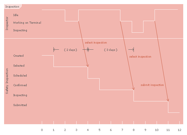
"Inspection in software engineering, refers to peer review of any work product by trained individuals who look for defects using a well defined process. An inspection might also be referred to as a Fagan inspection after Michael Fagan, the creator of a very popular software inspection process. ...
An inspection is one of the most common sorts of review practices found in software projects. The goal of the inspection is for all of the inspectors to reach consensus on a work product and approve it for use in the project. Commonly inspected work products include software requirements specifications and test plans. In an inspection, a work product is selected for review and a team is gathered for an inspection meeting to review the work product. A moderator is chosen to moderate the meeting. Each inspector prepares for the meeting by reading the work product and noting each defect. The goal of the inspection is to identify defects. In an inspection, a defect is any part of the work product that will keep an inspector from approving it. For example, if the team is inspecting a software requirements specification, each defect will be text in the document which an inspector disagrees with." [Software inspection. Wikipedia]
The UML timing diagram example "Inspection" was created using the ConceptDraw PRO diagramming and vector drawing software extended with the Rapid UML solution from the Software Development area of ConceptDraw Solution Park.
UML timing diagram
The vector stencils library "UML timing diagrams" contains 15 symbols for the ConceptDraw PRO diagramming and vector drawing software.
"The following nodes and edges are typically drawn in a UML timing diagram: lifeline, state or condition timeline, destruction event, duration constraint, time constraint. ...
Lifeline is a named element which represents an individual participant in the interaction. ... lifelines represent only one interacting entity. ...
Lifeline on the timing diagrams is represented by the name of classifier or the instance it represents. It could be placed inside diagram frame or a "swimlane". ...
Timing diagram could show states of the participating classifier or attribute, or some testable conditions, such as a discrete or enumerable value of an attribute. ...
UML also allows the state/ condition dimension be continuous. It could be used in scenarios where entities undergo continuous state changes, such as temperature or density. ...
Destruction occurrence is a message occurrence which represents the destruction of the instance described by the lifeline. It may result in the subsequent destruction of other objects that this object owns by composition. No other occurrence may appear after the destruction event on a given lifeline.
Complete UML name of the occurrence is destruction occurrence specification. Until UML 2.4 it was called destruction event, and earlier - stop.
The destruction event is depicted by a cross in the form of an X at the end of a timeline. ...
Duration constraint is an interval constraint that refers to a duration interval. The duration interval is duration used to determine whether the constraint is satisfied.
The semantics of a duration constraint is inherited from constraints. If constraints are violated, traces become negative which means that system is considered as failed.
Duration constraint is shown as some graphical association between a duration interval and the constructs that it constrains. ...
Time constraint is an interval constraint that refers to a time interval. The time interval is time expression used to determine whether the constraint is satisfied.
The semantics of a time constraint is inherited from constraints. All traces where the constraints are violated are negative traces, i.e., if they occur, the system is considered as failed.
Time constraint is shown as graphical association between a time interval and the construct that it constrains. Typically this graphical association is a small line, e.g., between an occurrence specification and a time interval." [uml-diagrams.org/ timing-diagrams.html]
The example "Design elements - UML timing diagrams" is included in the Rapid UML solution from the Software Development area of ConceptDraw Solution Park.
UML timing diagram symbols

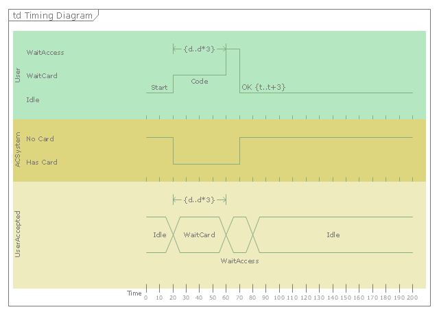
"A timing diagram in the Unified Modeling Language 2.0 is a specific type of interaction diagram, where the focus is on timing constraints.
Timing diagrams are used to explore the behaviors of objects throughout a given period of time. A timing diagram is a special form of a sequence diagram. The differences between timing diagram and sequence diagram are the axes are reversed so that the time is increased from left to right and the lifelines are shown in separate compartments arranged vertically.
There are two basic flavors of timing diagram: the concise notation, and the robust notation." [Timing diagram (Unified Modeling Language). Wikipedia]
This UML timing diagram example was created using the ConceptDraw PRO diagramming and vector drawing software extended with the Rapid UML solution from the Software Development area of ConceptDraw Solution Park.
UML timing diagram
HelpDesk
How to Create a Bank ATM Use Case Diagram

ConceptDraw PRO diagramming software, enhanced and expanded with the ATM UML Diagrams solution, offers the full range of icons, templates and design elements needed to faithfully represent ATM and banking information system architecture using UML standards. The ATM UML Diagrams solution is useful for beginner and advanced users alike. More experienced users will appreciate a full range of vector stencil libraries and ConceptDraw PRO's powerful software, that allows you to create your ATM UML diagram in a matter of moments.
- Timing diagram | Diagramming Software for Design UML Timing ...
- Diagramming Software for Design UML Timing Diagrams | Timing ...
- UML timing diagram template | Timing diagram | Diagramming ...
- Timing diagram | Diagramming Software for Design UML Timing ...
- Rapid UML | UML Tool & UML Diagram Examples | Timing diagram ...
- Timing diagram | UML Timing Diagram , Design Elements ...
- Diagramming Software for Design UML Timing Diagrams ...
- Diagramming Software for Design UML Timing Diagrams | Timing ...
- Think. Act. Accomplish. | Product Overview | UML Timing Diagram ...
- Timing diagram | Diagramming Software for Design UML Timing ...
- UML Diagrams with ConceptDraw PRO | UML Sequence Diagram ...
- Timing diagram | UML Collaboration Diagram (UML2.0 ...
- UML Tool & UML Diagram Examples | Rapid UML | UML Class ...
- UML Diagram Visio | Rapid UML | UML Software | Visio Timing ...
- UML Tool & UML Diagram Examples | Rapid UML | UML Business ...
- UML Tool & UML Diagram Examples
- UML Tool & UML Diagram Examples | UML Diagram | ConceptDraw ...
- UML Sequence Diagram | Diagramming Software for designing ...
- UML Sequence Diagram . Design Elements | UML Diagrams with ...
- UML Diagrams with ConceptDraw PRO | Diagramming Software for ...
- ERD | Entity Relationship Diagrams, ERD Software for Mac and Win
- Flowchart | Basic Flowchart Symbols and Meaning
- Flowchart | Flowchart Design - Symbols, Shapes, Stencils and Icons
- Flowchart | Flow Chart Symbols
- Electrical | Electrical Drawing - Wiring and Circuits Schematics
- Flowchart | Common Flowchart Symbols
- Flowchart | Common Flowchart Symbols