Example of DFD for Online Store (Data Flow Diagram)

Example of DFD for Online Store shows the Data Flow Diagram for online store and interactions between the Visitors, Customers and Sellers, as well as Website Information and User databases.

Data Flow Diagram Model

State Diagram Example — Online Store

This sample shows the work of the online store and can be used for the understanding of the online shopping processes, for projection and creating of the online store.
DFD Library System

UML Sample Project

Wireframing
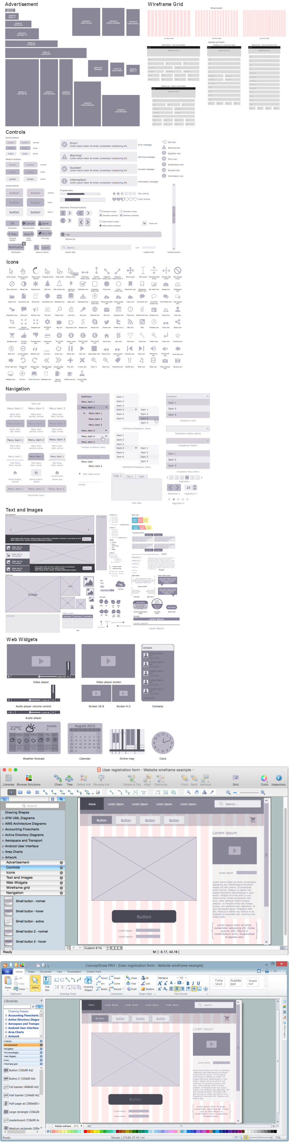
ConceptDraw DIAGRAM extended with Website Wireframe solution from the Software Development area is the best wireframing software. Using the wireframe tools, libraries of vector objects, template and examples which offers a Website Wireframe solution, you will easily design the websites wireframes of any complexity.
UML Diagram for Mac

UML Deployment Diagram. Design Elements

ConceptDraw has 393 vector stencils in the 13 libraries that helps you to start using software for designing your own UML Diagrams. You can use the appropriate stencils of UML notation from UML Deployment library.
Diagramming Software for Design UML Object Diagrams

ConceptDraw Rapid UML solution delivers libraries contain pre-designed objects fit UML notation, and ready to draw professional UML Object Diagram.

UML Activity Diagram

Use ConceptDraw DIAGRAM diagramming and vector drawing software enhanced with Rapid UML solution from ConceptDraw Solution Park to create your own UML activity diagrams that show the business and operational workflows of components and overall flow of control in your systems. Such software provides coloring UML diagrams for various purposes and simplifying work of the engineers.
 Data Flow Diagrams (DFD)
Data Flow Diagrams solution extends ConceptDraw DIAGRAM software with templates, samples and libraries of vector stencils for drawing the data flow diagrams (DFD).
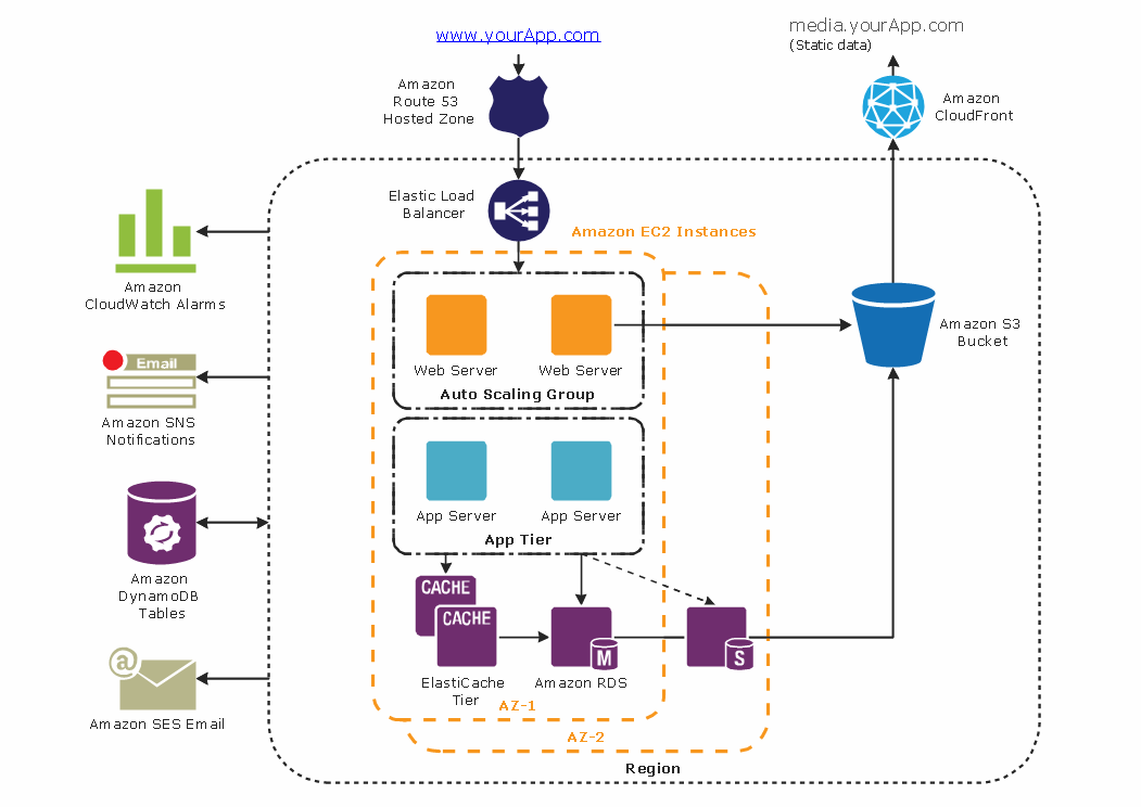
Diagramming tool - Amazon Web Services and Cloud Computing Diagrams
UML Class Diagram Generalization Example UML Diagrams

This sample describes the use of the classes, the generalization associations between them, the multiplicity of associations and constraints. Provided UML diagram is one of the examples set that are part of Rapid UML solution.
UML Component Diagram

- Draw System Flow Diagram For Online Shopping System
- Draw The System Flow For Online Shopping
- Draw System Flow Diagram For Online Shopping Pdf
- Online Shopping System Flow Chart
- System Flow Chart From Online Shoping
- Class Diagram Online Shopping System
- Online Shopping System Project Data Flow Diagram
- Pdf Of All Uml Diagrams Of Online Shopping System
- System Flow Diagram For Online Shopping
- System Flow Diagram For Online Shopping System
- Draw A System Flow Diagram For Online Shopping System
- Sample Data Flow Diagram For Online Shop
- Pert Chart For Online Shopping System
- Eer Diagram Of Online Shopping System
- Dfd Diagram For Online Shopping System
- UML Component Diagram Example - Online Shopping | State ...
- Flow Chart Online Shopping
- System Flow Diagram For Online Shopping System In Software
- Dfd For Online Shopping System Pdf
- Flow Chart Of Online Shopping Website
- ERD | Entity Relationship Diagrams, ERD Software for Mac and Win
- Flowchart | Basic Flowchart Symbols and Meaning
- Flowchart | Flowchart Design - Symbols, Shapes, Stencils and Icons
- Flowchart | Flow Chart Symbols
- Electrical | Electrical Drawing - Wiring and Circuits Schematics
- Flowchart | Common Flowchart Symbols
- Flowchart | Common Flowchart Symbols