Software Diagram Examples and Templates

Software Development area of ConceptDraw Solution Park provides 5 solutions:
Data Flow Diagrams, Entity-Relationship Diagram (ERD), Graphic User Interface, IDEFO Diagrams, Rapid UML.
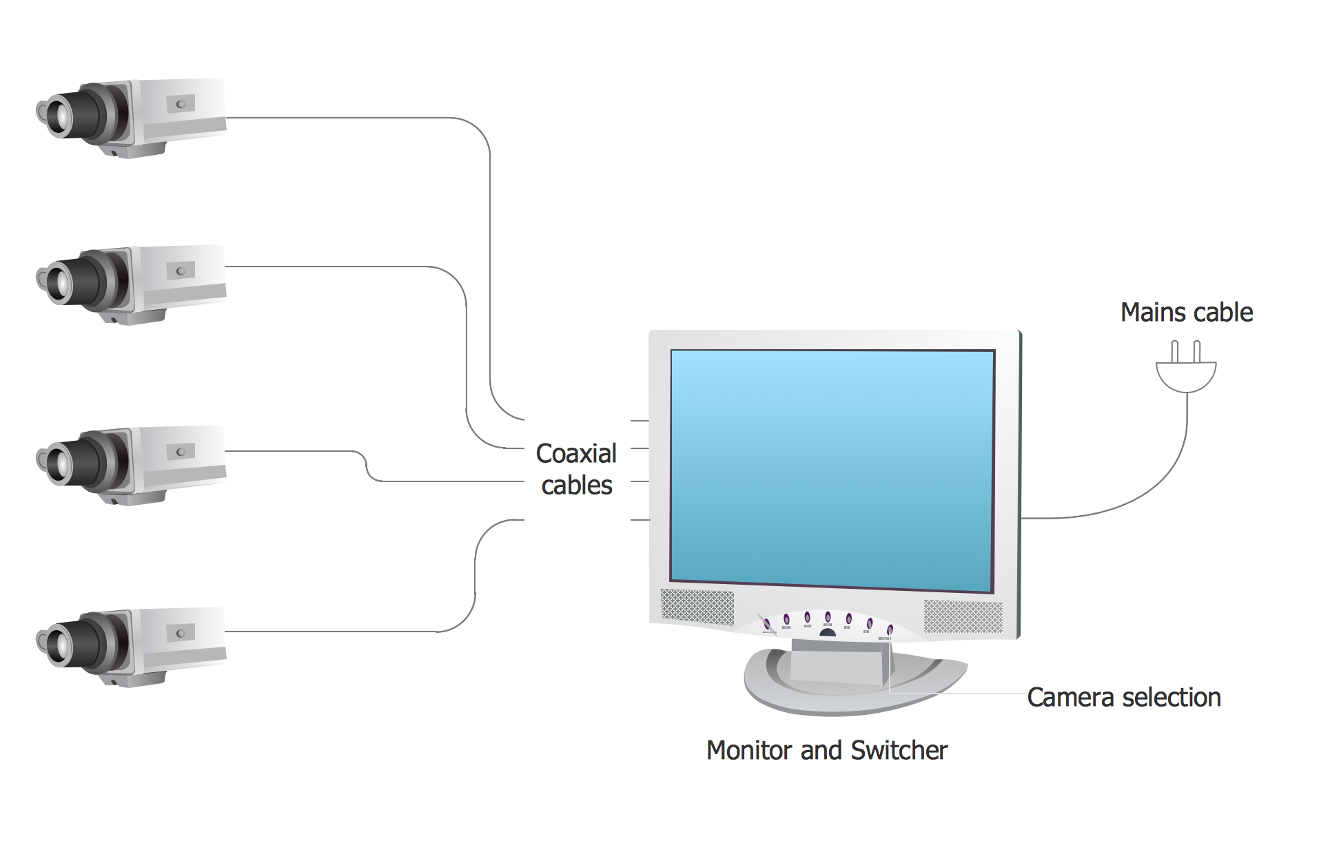
Basic CCTV System Diagram. CCTV Network Diagram Example
Process Flowchart


UML Use Case Diagram Example. Registration System

This sample was created in ConceptDraw DIAGRAM diagramming and vector drawing software using the UML Use Case Diagram library of the Rapid UML Solution from the Software Development area of ConceptDraw Solution Park.
This sample shows the types of user’s interactions with the system and is used at the registration and working with the database system.
UML Deployment Diagram Example - ATM System UML diagrams

This sample shows the work of the ATM (Automated Teller Machine) banking system that is used for service and performing of the banking transactions using ATMs. System engineers can use comprehensive UML diagrams solution.
Data Flow Diagram Examples

UML Tool & UML Diagram Examples

Solution RapidUML from Software Development area of ConceptDraw Solution Park provides templates, examples and 13 vector stencils libraries for drawing all types of UML 1.x and 2.x diagrams using ConceptDraw DIAGRAM diagramming and vector drawing software.
Use these UML diagram templates and examples to quickly start drawing your own UML diagrams.
Entity Relationship Diagram Examples

ConceptDraw gives the ability to describe a database using the Entity-Relationship model. Entity-Relationship Diagram solution includes icons advocated by Chen's and Crow’s Foot notation that can be used when describing a database.

UML Class Diagram Example for GoodsTransportation System
This sample shows the concept of working of the transport company and is used by transport companies, carriers at the transportation of various goods.
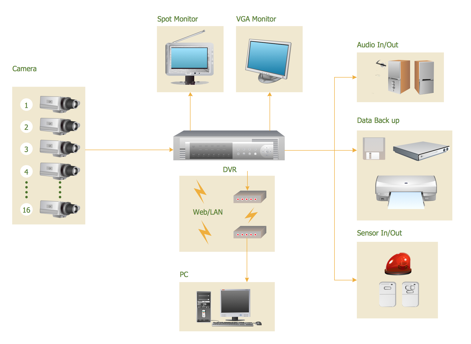
CCTV Surveillance System Diagram. CCTV Network Diagram Example
- System Diagrams Examples
- UML Deployment Diagram Example - ATM System UML diagrams ...
- System Chart In Textile Shop Any Examples
- Detailed Entity Relationship Diagram Example For Management
- Basic CCTV System Diagram . CCTV Network Diagram Example ...
- UML use case diagram - Trading system usage scenarios | UML use ...
- UML Use Case Diagram Example Registration System | UML activity ...
- UML Deployment Diagram Example
- ATM UML Diagrams | Uml Diagrams Examples Atm System
- 4 Level pyramid model diagram - Information systems types | 5 Level ...
- ERD | Entity Relationship Diagrams, ERD Software for Mac and Win
- Flowchart | Basic Flowchart Symbols and Meaning
- Flowchart | Flowchart Design - Symbols, Shapes, Stencils and Icons
- Flowchart | Flow Chart Symbols
- Electrical | Electrical Drawing - Wiring and Circuits Schematics
- Flowchart | Common Flowchart Symbols
- Flowchart | Common Flowchart Symbols