Entity Relationship Diagram Symbols

ERD symbols used for professional ERD drawing are collected in libraries from the Entity-Relationship Diagram (ERD) solution for ConceptDraw DIAGRAM.
Components of ER Diagram

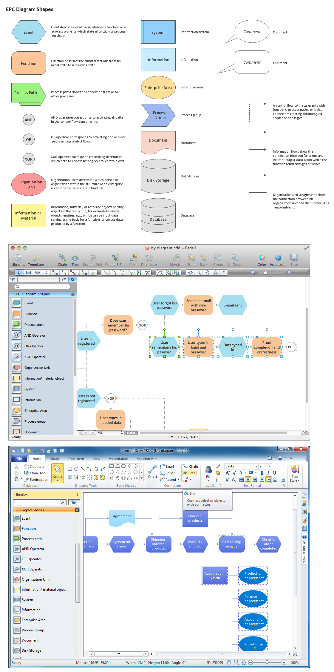
Graphical Symbols to use in EPC diagrams
ConceptDraw DIAGRAM - software that reduces the time needed to create a business process model.
Entity Relationship Diagram - ERD - Software for Design Crows Foot ER Diagrams
_Win_Mac.png)

ConceptDraw DIAGRAM ER Diagram Tool

ConceptDraw ER Diagram Tool works across any platform, meaning you never have to worry about compatibility again. ConceptDraw DIAGRAM allows you to make Entity-Relationship Diagram (ERD) on PC or macOS operating systems.
Data Flow Diagram Symbols. DFD Library

Notation & Symbols for ERD

A complete set of work flow shapes, notation & symbols for ERD, entity relationship stencils, included in Entity-Relationship Diagram (ERD) solution for ConceptDraw DIAGRAM software, makes drawing diagrams based on ERD notation as smooth as possible.
Entity Relationship Diagram Examples

ConceptDraw DIAGRAM diagramming and vector drawing software gives the ability to describe a database using the Entity-Relationship model. Entity-Relationship Diagram(ERD) solution from the Software Development area supplies the ConceptDraw DIAGRAM with icons advocated by Chen's and Crow’s Foot notation that can be used when describing a database.
Database Flowchart Symbols

ConceptDraw Software provides number of data-base chart libraries including major 49 vector symbols. Use these DFD flowchart symbol libraries to design data-base structure and models, use it to design data base process-oriented models, or simple data-oriented models. The are special drawing tools for making data flowcharts, data process diagrams, structured analysis diagrams, and information flow diagrams.
DFD Flowchart Symbols

- Entity Relationship Diagram Symbols
- Entity Relationship Diagram Symbols | Database Flowchart Symbols ...
- Entity - Relationship Diagram ( ERD ) | Accounting Information ...
- Entity Relationship Diagram Symbols | Data Flow Diagram
- Entity Relationship Diagram Symbols | Martin ERD Diagram | Data ...
- Data Flow Diagram Symbols . DFD Library | Entity Relationship ...
- Design elements - ERD (crow's foot notation) | Entity Relationship ...
- ERD Symbols and Meanings | EPC | Entity - Relationship Diagram ...
- UML Flowchart Symbols | Entity Relationship Diagram Symbols ...
- Activities When Creating Erd Infomation Systems
- ERD | Entity Relationship Diagrams, ERD Software for Mac and Win
- Flowchart | Basic Flowchart Symbols and Meaning
- Flowchart | Flowchart Design - Symbols, Shapes, Stencils and Icons
- Flowchart | Flow Chart Symbols
- Electrical | Electrical Drawing - Wiring and Circuits Schematics
- Flowchart | Common Flowchart Symbols
- Flowchart | Common Flowchart Symbols