Electrical Symbols — Composite Assemblies

26 libraries of the Electrical Engineering Solution of ConceptDraw DIAGRAM make your electrical diagramming simple, efficient, and effective. You can simply and quickly drop the ready-to-use objects from libraries into your document to create the electrical diagram.
Electrical Symbols — Stations

26 libraries of the Electrical Engineering Solution of ConceptDraw DIAGRAM make your electrical diagramming simple, efficient, and effective. You can simply and quickly drop the ready-to-use objects from libraries into your document to create the electrical diagram.
Electrical Symbols, Electrical Diagram Symbols

This solution provides 26 libraries which contain 926 electrical symbols from electrical engineering: Analog and Digital Logic, Composite Assemblies, Delay Elements, Electrical Circuits, Electron Tubes, IGFET, Inductors, Integrated Circuit, Lamps, Acoustics, Readouts, Logic Gate Diagram, MOSFET, Maintenance, Power Sources, Qualifying, Resistors, Rotating Equipment, Semiconductor Diodes, Semiconductors, Stations, Switches and Relays, Terminals and Connectors, Thermo, Transformers and Windings, Transistors, Transmission Paths,VHF UHF SHF.
Cisco Network Design. Cisco icons, shapes, stencils, symbols and design elements

Cisco LAN. Cisco icons, shapes, stencils and symbols

Cisco Routers. Cisco icons, shapes, stencils and symbols

Any planning begins with an analysis of the business requirements to the final system. Basic network parameters, which should be assessed are the scalability, accessibility, cost, speed and safety.
Speed and cost are often mistaken for the most important parameters, and the rest of the parameters aren't even remembered. This is not entirely correct. Initially, it is necessary to assess the business plans for the future, because sometimes it is more profitable to invest more money in the beginning. If the business is to develop, then, consequently, demands on
Cisco WAN. Cisco icons, shapes, stencils and symbols

Electrical Drawing Software and Electrical Symbols

Electrical Drawing Software provides the 26 stencils libraries of ready-to-use predesigned vector electrical symbols, templates and samples that make your electrical drawing quick, easy and effective.
Ring Network Topology

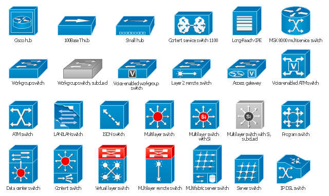
The vector stencils library "Cisco switches and hubs" contains 26 symbols for drawing computer network diagrams using the ConceptDraw PRO diagramming and vector drawing software.
"A network switch (sometimes known as a switching hub) is a computer networking device that is used to connect many devices together on a computer network. A switch is considered more advanced than a hub because a switch will only send a message to the device that needs or requests it, rather than broadcasting the same message out of each of its ports.
A switch is a multi-port network bridge that processes and forwards data at the data link layer (layer 2) of the OSI model. Some switches have additional features, including the ability to route packets. These switches are commonly known as layer-3 or multilayer switches. Switches exist for various types of networks including Fibre Channel, Asynchronous Transfer Mode, InfiniBand, Ethernet and others." [Network switch. Wikipedia]
"An Ethernet hub, active hub, network hub, repeater hub, multiport repeater or hub is a device for connecting multiple Ethernet devices together and making them act as a single network segment. It has multiple input/ output (I/ O) ports, in which a signal introduced at the input of any port appears at the output of every port except the original incoming. A hub works at the physical layer (layer 1) of the OSI model. The device is a form of multiport repeater. Repeater hubs also participate in collision detection, forwarding a jam signal to all ports if it detects a collision.
Some hubs may also come with a BNC and/ or Attachment Unit Interface (AUI) connector to allow connection to legacy 10BASE2 or 10BASE5 network segments." [Ethernet hub. Wikipedia]
The example "Design elements - Cisco switches and hubs" is included in the Cisco Network Diagrams solution from the Computer and Networks area of ConceptDraw Solution Park.
Cisco switches and hubs symbols
- Symbol For Repeater
- Logical Symbol Of Repeater
- Network Repeater Symbol
- Repeater Logic Symbol
- Repeater Symbol Cisco
- Electrical Symbols — Composite Assemblies | Composite ...
- Wireless Reapeter Symbol
- Electrical Symbols — Composite Assemblies | Design elements ...
- Cisco Layer 2 Switch Symbol
- Network Icon | Local area network (LAN). Computer and Network ...
- ERD | Entity Relationship Diagrams, ERD Software for Mac and Win
- Flowchart | Basic Flowchart Symbols and Meaning
- Flowchart | Flowchart Design - Symbols, Shapes, Stencils and Icons
- Flowchart | Flow Chart Symbols
- Electrical | Electrical Drawing - Wiring and Circuits Schematics
- Flowchart | Common Flowchart Symbols
- Flowchart | Common Flowchart Symbols