Basic Flowchart Symbols and Meaning
Flowchart Symbols and Meaning - Provides a visual representation of basic flowchart symbols and their proposed use in professional workflow diagram, standard process flow diagram and communicating the structure of a well-developed web site, as well as their correlation in developing on-line instructional projects. See flowchart's symbols by specifics of process flow diagram symbols and workflow diagram symbols.
UML Tool & UML Diagram Examples
The classical design of any automated process is UML diagrams that provide wide graphical ways to present all aspects of automation.Solution RapidUML from Software Development area of ConceptDraw Solution Park provides templates, examples and 13 vector stencils libraries for drawing all types of UML 1.x and 2.x diagrams using ConceptDraw PRO diagramming and vector drawing software.
Use these UML diagram templates and examples to quickly start drawing your own UML diagrams.
Active Directory Diagram
Active Directory Diagram represents the scheme of correlations of service components with the preset degree of the detailed elaboration. Such diagram lets plan and service the existing network quicker and more qualitatively and presents the clear picture of the network structure in graphical format.With the help of ConceptDraw PRO extended with Active Directory Diagrams Solution from the Computer and Networks Area you can easily and quickly create the highly detailed Active Directory Diagram.
HelpDesk
How to Create a Bank ATM Use Case Diagram
UML diagrams are often used in banking management for documenting a banking system. In particular, the interaction of bank customers with an automated teller machine (ATM) can be represented in a Use Case diagram. Before the software code for an ATM, or any other system design, is written, it is necessary to create a visual representation of any object-oriented processes. This is done most effectively by creating a Unified Modeling Language (UML) diagram, using object-oriented modeling. UML works as a general purpose modeling language for software engineers or system analysts, offering a number of different diagram styles with which to visually depict all aspects of a software system.ConceptDraw PRO diagramming software, enhanced and expanded with the ATM UML Diagrams solution, offers the full range of icons, templates and design elements needed to faithfully represent ATM and banking information system architecture using UML standards. The ATM UML Diagrams solution is useful for beginner and advanced users alike. More experienced users will appreciate a full range of vector stencil libraries and ConceptDraw PRO's powerful software, that allows you to create your ATM UML diagram in a matter of moments.
UML Diagram
UML defines 13 types of diagrams: class (package), object, use case, sequence, collaboration, component, state machine, timing, interaction overview, composite structure, activity, and deployment.Create unified modeling language (UML) diagrams with ConceptDraw.
ConceptDraw Arrows10 Technology
How should diagramming software work? Is it possible to develop a diagram as quickly as the ideas come to you? The innovative ConceptDraw Smart Connectors Technology - This is more than enough versatility to draw any type of diagram with any degree of complexity.Connection points are necessary for diagramming network, flowchart and organizational charts. In ConceptDraw you connect shapes by attaching, or snapping and gluing, connectors to shape connection points.
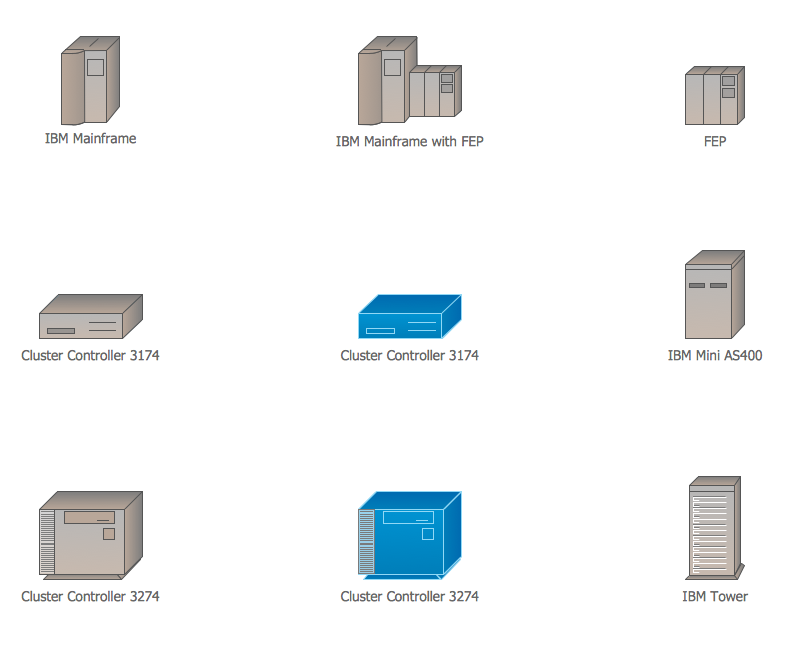
Cisco IBM. Cisco icons, shapes, stencils and symbols
The ConceptDraw vector stencils library Cisco IBM contains equipment symbols for drawing the computer network diagrams.Entity Relationship Diagram Software Engineering
Entity Relationship Diagram (aka ERD, ER Diagram, E-R Diagram) is a well-tried software engineering tool for data modeling, system design and illustrating the logical structure of databases.Professional ERD drawing is an essential software engineering method for database modeling. ConceptDraw PRO as a powerful Entity Relationship Diagram Software Engineering offers the tools of Entity-Relationship Diagram (ERD) solution from Software Development area of ConceptDraw Solution Park.
Software Diagram Examples and Templates
ConceptDraw Pro is a powerful tool for business and technical diagramming.Software Development area of ConceptDraw Solution Park provides 5 solutions:
Data Flow Diagrams, Entity-Relationship Diagram (ERD), Graphic User Interface, IDEFO Diagrams, Rapid UML.
UML Class Diagram Notation
When it comes to system construction, a class diagram is the most widely used diagram. UML Class Diagrams is a type of static structure diagram that is used for general conceptual modeling of the systematics of the application. Such a diagram would illustrate the object-oriented view of a system . The object orientation of a system is indicated by a class diagram. It describes the structure of a system by showing the general issues,classes of a system, attributes, operations, interfaces, inheritance, and the relationships between them.- Bank Sequence Diagram | UML activity diagram - Cash withdrawal ...
- Design elements - Analog and digital logic | State Diagram Example ...
- UML activity diagram - Cash withdrawal from ATM | ATM UML ...
- UML state machine diagram - Template | Vector stencils library ...
- State Diagram Calculator
- State Machine Diagram | UML Use Case Diagram Example ...
- UML Diagram of Parking | UML Use Case Diagram Example Social ...
- Controller Flow Chart Example
- Home area networks (HAN). Computer and Network Examples ...
- Audit Flowcharts | PM Dashboards | Sequence Diagram For Finance ...
- ERD | Entity Relationship Diagrams, ERD Software for Mac and Win
- Flowchart | Basic Flowchart Symbols and Meaning
- Flowchart | Flowchart Design - Symbols, Shapes, Stencils and Icons
- Flowchart | Flow Chart Symbols
- Electrical | Electrical Drawing - Wiring and Circuits Schematics
- Flowchart | Common Flowchart Symbols
- Flowchart | Common Flowchart Symbols


